Email:Mannan.Ali@physics.org Chapter 5: Magnetic Anisotropy In Amorphous Films
Web: http://members.xoom.com/MannansZone/thesis.html


5.0 Magnetic Anisotropy In Amorphous Films

This chapter is concerned with the magnetic anisotropy of amorphous FeSiBC films which have been deposited by RF magnetron sputtering, mainly at the optimised sputtering parameters of 75W and 4mTorr (Chapter 5). The magnetic properties were investigated mainly using the magneto-optical Kerr effect, with both point hysteresis measurements and domain imaging. A significant in-plane anisotropy was observed in the as-deposited films, which has been attributed to the residual field from the magnetron sputtering source. The effects of various treatments on the films are investigated, including the use of forming fields, stress, and thermal processing. The deliberate introduction of stress into these materials is found to allow excellent control of both the direction and magnitude of the magnetic anisotropy. The treatments are evaluated for their potential to control the anisotropy in magnetostrictive device applications.

A simple new technique is also described for the measurement of the saturation magnetostriction in amorphous thin films deposited onto rigid substrates. The method is based on mechanically introducing a small curvature in the substrate either during the deposition (strained growth) or post-deposition. The strain induced anisotropy is measured using the magneto-optical Kerr effect. Quantification of the film strain is obtained using optical interference and stylus measurements; coupled with mechanical finite element modelling, this allowed the saturation magnetostriction to be determined. No information concerning the mechanical properties of the substrate are required and, providing that the Young’s modulus and Poisson’s ratio of the film are known accurately, the values of magnetostriction obtained are both accurate and absolute. It is envisaged that the technique could be applied to a wide variety of films deposited onto commercially important substrates. Here, it is applied to amorphous FeSiBC films deposited onto glass and silicon substrates. A high degree of control is also demonstrated in tailoring the anisotropy field, by the technique of substrate straining.

5.1 Introduction

Most ferromagnetic thin films display a uniaxial anisotropy in plane irrespective of whether they are produced by vapour or sputter deposition techniques. This anisotropy is not always obvious from measurement of bulk hysteresis loops, especially if the film consists of a complex multi-domain structure, where the magnetisation process across the entire film will not proceed by coherent moment rotation, even though each domain structure is uniaxially magnetised. These magnetised domain regions within the film can be seen from domain patterns using, for example, the magneto optical Kerr effect as described in Chapter 2 or point MOKE hysteresis loops if the domains are larger than the sampling area of the laser. The domain images show a tendency for domain walls to lie along preferred directions in the plane of the film. It is well known that the application of a magnetic field during the deposition has the effect of ensuring that the easy axis of magnetisation of the whole film is in the one direction (ie. uniaxial).


Growth and study of magnetostrictive FeSiBC thin films, for device applications, Mannan Ali (1999) 79
(Online Copy)


 Link bar
 Link bar

Email:Mannan.Ali@physics.org Chapter 5: Magnetic Anisotropy In Amorphous Films
Web: http://members.xoom.com/MannansZone/thesis.html


The importance of the magnetic anisotropy in magnetostrictive films is becoming increasingly significant, since these magnetically soft, amorphous films are being widely utilised in the production of a new generation of magnetic sensors and actuators [Ref. List (5.1)]. The incorporation of these materials into micro-electromechanical systems requires a good control of the magnetic anisotropy in sensor elements of various aspect ratios and thicknesses. For actuators, the maximum magnetostrictive deflection is obtained when the magnetic moments are rotated coherently through 90°. Such a rotation is conveniently achieved by the application of an external magnetic field along the hard axis of a sample which has a well defined uniaxial anisotropy. It is therefore essential, not only from the point of view of sensor applications, but also from that of understanding the material’s magnetic behaviour, that the magnetic anisotropy of the material is understood, since the magnetic anisotropy strongly affects the magnetisation process and therefore the shape of the hysteresis loop, which is widely used to characterise magnetic materials.

5.2 Magnetocrystalline Anisotropy

Magnetic materials tend to display a directional dependence of their properties, and this is a consequence of the magnetic anisotropy. The magnetic anisotropy describes the preference of the magnetisation to lie in a particular direction. The magnetic anisotropy in crystalline materials has clearly been demonstrated where certain crystallographic directions are easy directions of magnetisation, whilst others are hard directions. This has been ascertained by the measurement of magnetisation curves. In the absence of any applied external magnetic field the magnetisation prefers to lie along an easy axis, since this minimises the magnetic energy of the system. The easy and hard directions can be distinguished by the magnetic field needed to achieve magnetic saturation. A prime example is a single crystal of Fe, where the <100> directions are easy axes of magnetisation, whilst the <111> directions are said to be hard axes of magnetisation [Cullity (1972)]. This form of magnetic anisotropy is referred to as the crystal anisotropy, or magnetocrystalline anisotropy, which is intrinsic to the material. The crystal anisotropy originates from the spin-orbit interaction where the electron spin is coupled to the electron orbit. When a magnetic field is applied to rotate the electron spins, it also attempts to reorientate the electron orbit which, however, is strongly coupled to the crystal lattice. The magnetic field or energy needed to rotate the electron spin’s (magnetisation) is known as the crystal anisotropy energy, which is the energy needed to overcome the spin-orbit interaction. The expression for the crystal anisotropy energy density for a cubic crystal can be expressed by equation (5.1) [Cullity (1972)]

Eq. (5.1)(5.1)

where K0, K1, K2… are the anisotropy constants, which are material dependent and ai are the directional cosines of the angle between the magnetisation and crystal axes. This intrinsic crystal anisotropy is not preserved in amorphous materials, since the crystal field rapidly averages to "zero" on a macroscopic


Growth and study of magnetostrictive FeSiBC thin films, for device applications, Mannan Ali (1999) 80
(Online Copy)


 Link bar
 Link bar

Email:Mannan.Ali@physics.org Chapter 5: Magnetic Anisotropy In Amorphous Films
Web: http://members.xoom.com/MannansZone/thesis.html


scale because of the amorphous arrangement of the atoms. On a local scale, it can be assumed that there is some "crystalline" anisotropy because of nearest neighbour interactions, which will be very of a short range, and therefore the average macroscopic crystal anisotropy is close to, or equal to, zero. It should be remembered that ferromagnetism is a result of the exchange energy which is mainly dominated by the interaction between adjacent electron spins and their separations. Instead a number of other (see below) magnetic anisotropies can exist, which are usually induced in some manner, giving rise to a magnetic anisotropy which is uniaxial in direction. This means that there is a single, preferred direction, which for films is usually in the plane of the film. The tendency for the magnetisation to lie along such an easy axis, can be expressed as an anisotropy energy density, EK, in a series of powers of sinq. The expression for the energy density for a uniaxial anisotropy is:

Eq. (5.2)(5.2)

where q is the angle between the easy axis, and the direction of the magnetisation MS, and Ku0, Ku1, Ku2,… are the uniaxial anisotropy constants. The first anisotropy constant, Ku0, which is independent of q is usually neglected since it gives no change in EK when the direction of the magnetisation changes; Ku2 and higher order terms can also be neglected because they are relatively small in comparison to Ku1. This gives the following approximate expression for the uniaxial magnetic anisotropy as

Eq. (5.3)(5.3)

where Ku is the uniaxial anisotropy constant. It can be seen from these expressions that the anisotropy energy is a minimum when the magnetisation lies along an easy axis (q=00, 1800), and is a maximum when magnetisation is perpendicular to the easy axis (q=900, 2700). The magnitude of the induced anisotropy is usually monitored by measuring the anisotropy constant Ku or the anisotropy field HK, which is related to the anisotropy constant:

Eq. (5.4)(5.4)

where Ms is the saturation magnetisation and m0 is the permeability of free space. In this thesis the author has mainly used the anisotropy field when making comparisons of the magnitude of the uniaxial anisotropy present in the FeSiBC films, since the values were obtained from the measured hysteresis loops.


Growth and study of magnetostrictive FeSiBC thin films, for device applications, Mannan Ali (1999) 81
(Online Copy)


 Link bar
 Link bar

Email:Mannan.Ali@physics.org Chapter 5: Magnetic Anisotropy In Amorphous Films
Web: http://members.xoom.com/MannansZone/thesis.html


5.3 Shape Anisotropy

The shape anisotropy results from the demagnetising fields which occur within a magnetised material. The shape of the sample has the effect of creating directions in which it is easier to magnetise the sample, and this is governed by the demagnetising field, Hd, which, in the material, points in the opposite direction to the magnetisation and the applied field. For instance, a smaller field is required to magnetise a long cylindrical magnetic rod along its length, because of the smaller demagnetising field, compared to the magnetic field required to magnetise the rod along a diameter. If one thinks in terms of magnetic poles, the strength of the demagnetising field depends upon the separation between these opposite magnetic poles. The poles generated at the ends of a rod are much further apart, giving rise to a small demagnetising field, whereas the magnetic poles will be much closer together when the rod is magnetised across its diameter, thus producing a larger demagnetising field. The demagnetising field depends solely on the magnetisation and the demagnetising factor, and is expressed as

Eq. (5.5)(5.5)

where Nd (0£Nd£1) is the demagnetising factor which is shape dependent, and M is the magnetisation. The Nd term is calculated solely from the geometry of the sample and can only be calculated exactly for an ellipsoid. The energy associated with this demagnetising field can be expressed as follows, and is referred to as the magnetostatic energy density.

Eq. (5.6)(5.6)

The shape anisotropy has an obvious importance in thin films, since there is a significant shape anisotropy because of the thickness of the film. It is well known that the magnetisation usually lies in-plane for a film in the absence of any crystal anisotropy or any other anisotropy which would cause the magnetisation to lie out of plane. In general, a thin film can be approximated by a flat ellipsoid or an oblate spheroid; this allows one to determine approximately the demagnetising factors for a thin film system. The demagnetising factor for an oblate spheroid [Craik (1995)] with the magnetisation in the plane of the film is given by

Eq. (5.7)(5.7)
Eq. (5.8)(5.8)


Growth and study of magnetostrictive FeSiBC thin films, for device applications, Mannan Ali (1999) 82
(Online Copy)


 Link bar
 Link bar

Email:Mannan.Ali@physics.org Chapter 5: Magnetic Anisotropy In Amorphous Films
Web: http://members.xoom.com/MannansZone/thesis.html


Polarised light

Figure 5.1: (a) Illustration of an oblate spheroid, to approximate a thin film. In general thin films tend be square, or circular. A photograph of a 500nm thick circular FeSiBC film 1cm diameter is also shown, which was deposited onto square glass substrate through a circular mask. (b) Domain image from a circular demagnetised FeSiBC film.

where q is the ratio of the of the diameter (d) of the spheroid to its thickness (t) as shown in Figure 5.1. This is a reasonable approximation for the films which were typically investigated in this thesis; the films were generally either rectangular (mainly square), or circular as shown in Figure 5.1. Using equation (5.6), and the typical values of d=1cm, t=500nm the demagnetising factor, Nd, in the plane of the film is of the order of 3.9´10-5. Essentially, the in-plane demagnetising factor is equal to zero and the demagnetising factor perpendicular to the plane of the film is therefore equal to one (Nx+Ny+Nz=1). Hence the easy-axis is in the plane of the film, whilst the hard axis is perpendicular to the plane of the film. This means that any competing anisotropy, or an applied field, must overcome the demagnetising field which is equal to the magnetisation M (Eq. 5.5), in order to rotate the magnetisation out of the plane of the film. It is therefore important to be aware of the shape anisotropy in the design process of thin film sensors in situations where the x-y dimensions of the film approach the thickness of the film, since the in-plane demagnetising field will no longer be negligible. The magnetic field, Hint, the sensor will experience in this situation will be

Eq. (5.9)(5.9)

where Happl is the external applied magnetic field. The shape anisotropy can cause the sensor to perform differently compared with measurements made on much larger devices.

Another anisotropy which is related to the shape of the film, is the surface anisotropy. In very thin films (<5nm) the surface or the film/substrate interface can give rise to a significant surface anisotropy [Gradmann (1986), Mattheis et al (1999)]; this can strongly influence the magnetic properties when the surface to volume ratio is comparable with or larger than that of the film thickness. The surface anisotropy is due to the abrupt change in the structural and chemical environment at the surface and can cause the magnetisation to point out of the plane of the film. Most thin film sensors tend be 100nm or thicker to ensure a good signal to noise ratio.

However, the absence of any shape anisotropy in the plane of the film (d>>t) and/or any significant magnetocrystalline anisotropy in the amorphous films, does not imply that all directions for the magnetisation within the plane of the film are energetically equal, as is shown in Figure 5.1b. In this instance, a circular FeSiBC film deposited in this study was repeatedly demagnetised; it was found from


Growth and study of magnetostrictive FeSiBC thin films, for device applications, Mannan Ali (1999) 83
(Online Copy)


 Link bar
 Link bar

Email:Mannan.Ali@physics.org Chapter 5: Magnetic Anisotropy In Amorphous Films
Web: http://members.xoom.com/MannansZone/thesis.html


domain imaging and hysteresis measurements that an approximately uniaxial anisotropy existed across the film, which was always orientated along the same direction. This anisotropy cannot be due to the shape anisotropy, since all directions should be equally magnetisable; therefore it is a result of some other anisotropy (see later).

5.4 Magnetostriction and Magnetoelasticity

When the state of magnetisation of a magnetic material is altered by an external magnetic field, it also experiences a change in its physical dimensions, provided that part or all of the magnetisation process occurs by magnetisation rotation as opposed to domain wall displacement. This change in dimension gives rise to a strain which is referred to as the magnetostriction as denoted by l (Eq. 5.10)

Eq. (5.10)(5.10)

where l is the length of the sample before the applied field and Dl is the change in length due to the applied field. The magnetostriction is due to the spin-orbit coupling which is also responsible for the magnetocrystalline anisotropy and they are both intrinsically related [Cullity (1972)]. This type of magnetostriction is known as longitudinal or linear magnetostriction. There are two main sources of magnetostriction, spontaneous magnetostriction which results from the ordering of the magnetic moments at the Curie temperature thus giving rise to a lattice strain, and the field induced magnetostriction, which is a consequence of the domain magnetisation being altered by an external magnetic field and which is due to the rotation of this lattice strain. The magnetostrictive strain l increases as a function of applied field up to the point of magnetic saturation and is known as the saturation magnetostriction, ls. It is defined as the fractional change in length between the demagnetised state and the magnetically saturated state. The magnetostrictive strain can have values which are either positive, negative, or in some cases, nearly zero depending upon the composition of the material; this means that, on application of a magnetic field, a positively magnetostrictive material will elongate in the direction of the applied field, whereas it will contract if it is negatively magnetostrictive. It is found that ls is anisotropic for crystalline materials and is therefore defined relative to the crystal axis along which the magnetisation lies. For amorphous materials the magnetostriction is isotropic and a simple expression relates the magnetostrictive strain to the magnetisation as shown in equation (5.11)

Eq. (5.11)(5.11)


Growth and study of magnetostrictive FeSiBC thin films, for device applications, Mannan Ali (1999) 84
(Online Copy)


 Link bar
 Link bar

Email:Mannan.Ali@physics.org Chapter 5: Magnetic Anisotropy In Amorphous Films
Web: http://members.xoom.com/MannansZone/thesis.html


Stress induced anisotropy

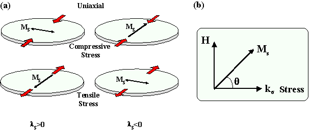
Figure 5.2: Illustration of stress induced anisotropy in positive and negative magnetostrictive materials. (a) Anisotropy induced when a uniaxial compressive or tensile stress exists. (b) Diagram illustrating the relationship between the stress and magnetisation.

where q, is the angle between the magnetisation and the direction of measurement. The maximum magnetostrictive strain has the value of 1.5ls and will occur when the magnetisation is rotated through 900 from magnetic saturation.

An important effect which is related to the magnetostriction is the inverse magnetostrictive or magnetoelastic effect, which deals with the effects of stress on the magnetisation of a magnetic material. In the presence of an external or internal stresses, the magnetisation will couple with the stresses via the magnetostriction to induce preferred directions for the magnetisation. This coupling between the magnetisation is dependent on the sign of ls and the stress as is illustrated in Figure 5.2a. For materials with ls>0 the magnetisation will rotate so as to lie along the direction of the uniaxial tensile stress, whereas it will lie perpendicular to a uniaxial compressive stress. The reverse is true for materials with ls<0 as is shown in Figure 5.2a.

The effect of stress in magnetostrictive materials is to induce a uniaxial magnetoelastic anisotropy. This source of magnetic anisotropy is very important in melt-spun ribbons and deposited films, where random micro-strains occur because of the growth process. This is more significant in melt-spun ribbons where it is unavoidable for stresses to be induced whereas, these growth-induced stresses can be minimised for films formed by sputter deposition as was shown in the previous chapter. If the material possesses a significant magnetostriction, then the magnetic properties are degraded because of the magnetisation coupling with these randomly orientated micro-strains. It should be noted that these randomly oriented strains will in most instances not produce an overall uniaxial anisotropy, unless there is a resultant uniaxial stress. The localised induced uniaxial anisotropies will have the effect of impeding the magnetisation rotation process and domain wall movement, since the applied field will need to overcome the magnetoelastic anisotropy energy Eme. The magnetoelastic energy density for materials with an isotropic magnetostriction is given by equation (5.12)

Eq. (5.12)(5.12)


Growth and study of magnetostrictive FeSiBC thin films, for device applications, Mannan Ali (1999) 85
(Online Copy)


 Link bar
 Link bar

Email:Mannan.Ali@physics.org Chapter 5: Magnetic Anisotropy In Amorphous Films
Web: http://members.xoom.com/MannansZone/thesis.html


where q is the angle between the magnetisation and the direction of the stress s. For materials where the magnetocrystalline anisotropy is not negligible, the direction of the magnetisation Ms will be controlled by both the magnetocrystalline and magnetoelastic anisotropy. If the crystal anisotropy K1>>lss, then the direction of the magnetisation is determined by K1 and the reverse is true if K1<<lss. In amorphous magnetostrictive materials, any magnetoelastic anisotropy will therefore control the direction of the magnetisation. The anisotropy field Hk associated with this uniaxial magnetoelastic anisotropy can be obtained by assuming a pure moment rotation. If one assumes that a stress s is applied to a positively magnetostrictive material, then the magnetisation will lie along this stress direction. On application of a magnetic field perpendicular to this induced uniaxial anisotropy, the magnetic energy density of the system can be expressed as

Eq. (5.13)(5.13)

where q is the angle between the magnetisation and the stress as shown in Figure 5.2b. The energy of the system must be a minimum at equilibrium

Eq. (5.14)(5.14)
Eq. (5.15)(5.15)

At the anisotropy field Hk=H, the magnetisation will lie at angle q=900, giving the expression for the anisotropy field in terms of the magnetoelastic anisotropy as

Eq. (5.16)(5.16)


Growth and study of magnetostrictive FeSiBC thin films, for device applications, Mannan Ali (1999) 86
(Online Copy)


 Link bar
 Link bar

Email:Mannan.Ali@physics.org Chapter 5: Magnetic Anisotropy In Amorphous Films
Web: http://members.xoom.com/MannansZone/thesis.html


5.5 Magnetic Anisotropy Induced During The Deposition

5.5.1 Growth Induced

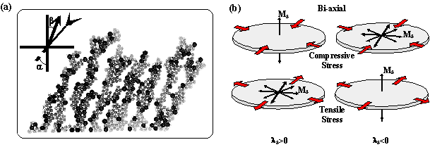
As has already been discussed in the previous chapter, the sputtering parameters have a significant effect on the structural and magnetic properties of a depositing film. At high sputtering energies (e.g. low pressures) the films are in a state of high compressive stress, whereas at low sputtering energies (e.g. high pressures), a columnar texture can develop in the depositing film [Shimada et al (1981), Leamy et al (1979)]. The columnar structure is formed by the self-shadowing of the incident atoms by the atoms already incorporated into the growing film. This columnar texture can give rise to a perpendicular anisotropy, because of the shape induced anisotropy of the columns; the magnetisation prefers to lie along the length of the columns because of the lower magnetostatic energy (Eq. (5.5)). The columns, which are formed by the process of columnar growth, are dependent upon the angle at which the impinging atoms arrive at surface of the film. An empirical expression relates the angles of impinging atoms, a, and the angle, b, at which the columns are formed, by equation (5.17) [Leamy et al (1978)].

Eq. (5.17)(5.17)

This is illustrated in Figure 5.3a, where the columnar structure for atoms impinging at a=300 is shown; in general, the formation of the columnar direction is not equal to the direction of the impinging atoms as expressed by equation (5.17). For the process of sputter deposition, as long as the target area is larger than the substrate area upon which the film is being deposited, then any columnar structure formation tends to be perpendicular. Columnar growth is strongly dependent on the deposition parameters and can develop in both sputter or evaporation deposition techniques. This columnar structure also has the effect of lowering the density of the films because of the more open structure which, in turn, has the effect of lowering saturation magnetisation, besides severely degrading the magnetic properties of the material by inducing a perpendicular anisotropy in thin films.

Columnar structure

Figure 5.3: Columnar structure for impinging atoms at a=300 to the substrate surface. [Image taken from Leamy et al (1978)]. (b) Anisotropy induced when a biaxial or higher order compressive or tensile stress exists.


Growth and study of magnetostrictive FeSiBC thin films, for device applications, Mannan Ali (1999) 87
(Online Copy)


 Link bar
 Link bar

Email:Mannan.Ali@physics.org Chapter 5: Magnetic Anisotropy In Amorphous Films
Web: http://members.xoom.com/MannansZone/thesis.html


For magnetostrictive films the intrinsic stresses induced during the deposition have a strong influence on the magnetic anisotropy. Films deposited at high sputtering kinetics show compressive stresses and no columnar structure formation [Shimada et al (1981)]. As discussed in the previous chapter, the intrinsic compressive stresses can result from any sputtering parameter which will increase the kinetics of the sputtered atoms. The magnetisation will couple with the stresses induced through the magnetostriction to produce a growth induced anisotropy which can be perpendicular to the plane of the film. The direction of the anisotropy induced is dependent upon the sign of the magnetostriction and also the sign and type of the stress (uniaxial, bi-axial, isotropic…) present within the film. This is more clearly illustrated in Figure 5.3b. For a perpendicular anisotropy to be induced in a film, the stresses induced therefore must be at least bi-axial in form to rotate the magnetisation out of the plane of the film as shown by Figure 5.3b. It is unlikely that a film deposited either by sputter or vapour deposition will develop a uniaxial stress direction, because of the random nature of the growth process. The intrinsic stresses which occur will be very random in direction on a local scale, giving rise to stresses which are likely to be isotropic in nature and which can account for the perpendicular anisotropy. It was shown in the previous chapter that FeSiBC films deposited onto glass cantilevers at low pressures, where found to be in a state of bi-axial compressive stress.

5.5.2 Stress Induced

Stresses in thin films can also be extrinsically induced due to the differing thermal expansion coefficients of the film and substrate as the film/substrate system cools after the deposition and contracts by different amounts. A film which is deposited onto a substrate which has a larger thermal expansion coefficient will be placed in a state of compressive stress, whereas a substrate with a lower thermal expansion coefficient will place the deposited film in state of tensile stress. If the stress is either bi-axial or isotropic, a uniaxial perpendicular anisotropy may be induced, depending on the sign of the magnetostriction (Fig. 5.3b). For substrates and films with similar expansion coefficients which are deposited at low deposition temperatures, this problem is usually avoided. However, stresses can also result from temperature differences which exist through the film and which cause different parts of the film to expand differently. This is especially important for substrates which are sputter cleaned prior to the deposition. If sufficient time is not allowed for the substrate temperature to cool, then the first few layers of the depositing film will be deposited onto a substrate at significantly increased temperature. This will therefore place the first few layers of the film in a state of stress as the substrate temperature equilibrates to the deposition temperature. This could severely effect the magnetic properties, especially in very thin films.

An alternative novel method of inducing a uniaxial magnetoelastic anisotropy during the deposition is to apply an external mechanical stress to the substrate [Ali et al (1999,1998), Garcia et al (1998)] which will induce a stress of the opposite sign; this is discussed in detail later in this chapter.


Growth and study of magnetostrictive FeSiBC thin films, for device applications, Mannan Ali (1999) 88
(Online Copy)


 Link bar
 Link bar

Email:Mannan.Ali@physics.org Chapter 5: Magnetic Anisotropy In Amorphous Films
Web: http://members.xoom.com/MannansZone/thesis.html


5.5.3 Field Induced

Inducing a uniaxial anisotropy by the application of a magnetic field parallel to the plane of the depositing film is a widely used technique. It is used in thin film sensors [Lu et al (1997), Morikawa et al (1997)] where it is preferable to align the domain magnetisation in a particular direction during the deposition; this removes the need to magnetically anneal the sensor at a much higher temperature to induce the required magnetic anisotropy. In some instances, depending on the type of sensor, it is not possible to substantially heat the sensor because of the delicate nature of other components which have been pre-fabricated onto the substrate for the operation of the sensor.

The origin of this uniaxial anisotropy is due to the directional ordering of like atom (e.g. Fe-Fe) pairs as described below for magnetic annealing. However, the ordering process in this situation occurs at an accelerated rate, even though the temperature of the depositing film is generally much lower in comparison. This is mainly due to the kinetic energies of the impinging sputtered atoms, which tend to be mobile at the surface of the film. This increased directional ordering is also assumed to be the reason why it is possible to induce much larger anisotropies in the depositing films, compared to conventional magnetic annealing were the directional ordering is not as high.

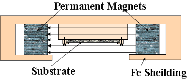
The magnetic field is usually provided by permanent magnets which are positioned on either side of the substrate or by a horse-shoe type of magnet arrangement. It is usual to shield the magnets by a grounded iron plate which prevents any stray field from the permanent magnets from disturbing the plasma dynamics. The shielding also prevents the magnets themselves from being sputtered. It is important that the applied field is parallel to the substrate surface and to minimise the number of flux lines which intersect (are not parallel to) the surface of the substrate and the plasma discharge. If the applied field is sufficiently large and parallel to the substrate as shown in Figure 5.4, then any secondary electrons on a collision path with the depositing film will be captured by the magnetic field, thus reducing the electron bombardment of the substrate. In the situation were the field lines have a transverse component to the substrate, there is an increase in the density of electrons arriving in the proximity of the substrate, which will therefore increase the likelihood of electron bombardment of the substrate [Ounadjela et al (1987)]. Ounadjela et al (1987) has shown that application of a field parallel to the substrate can reduce the substrate temperature by 1500C (see previous chapter). Obviously the application of a magnetic field will alter the sputtering dynamics and the surface mobility of the sputtered atoms; it is important to be aware of this fact. This generally means that the sputtering parameters need to be re-adjusted to account for this change.

Deposition of films in a magnetic field

Figure 5.4: Schematic arrangement of substrate holder for deposition of films in a magnetic field.


Growth and study of magnetostrictive FeSiBC thin films, for device applications, Mannan Ali (1999) 89
(Online Copy)


 Link bar
 Link bar

Email:Mannan.Ali@physics.org Chapter 5: Magnetic Anisotropy In Amorphous Films
Web: http://members.xoom.com/MannansZone/thesis.html


5.6 Post-Induced Magnetic Anisotropy

5.6.1 Magnetic Annealing

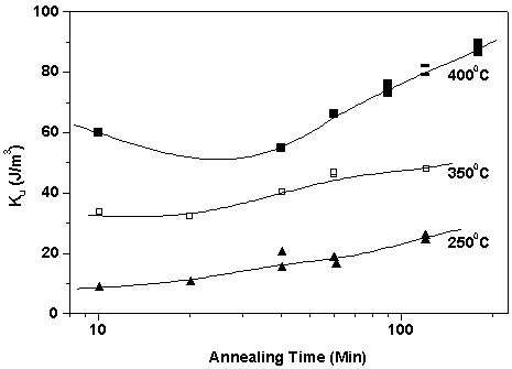
Magnetic field annealing is a well established method for inducing a uniaxial anisotropy in amorphous ribbons or films. It generally involves heating a magnetic sample below the Curie temperature, Tc, in the presence of a magnetic field which is sufficiently large to saturate the sample so as to ensure that a single domain exists. The origin of this induced magnetic anisotropy has been attributed to the short-range directional ordering of atomic pairs (e.g. Fe-Fe). The high temperature allows atomic diffusion on a local scale so that a preferred orientation minimises the energy of the system of like atomic pairs and aligns them parallel with the magnetic field. This directional order is frozen in place as the sample is allowed to cool in the presence of the magnetic field giving rise to an easy axis direction which is parallel to the magnetic field. The domain structure for such a demagnetised sample displays a strong preference for the domain walls to lie parallel to the induced easy axis. The anisotropy energy for the induced uniaxial anisotropy has the same form as that of equation (5.3). It is found that the anisotropy induced by field annealing is not particularly strong in amorphous ribbons [Lurborsky et al (1977)] or films [Ali et al (1998), Garcia et al (1999)]. Typical induced values of Ku range from 30-100 J/m3 (HK= 37-126 A/m) for the Fe-based ribbon alloys as found by Thomas et al (1992); it is found that the low anisotropy induced is sufficient to develop a well defined domain structure. The uniaxial anisotropy induced by the field annealing is a reversible process; annealing the sample just above the Curie temperature in the absence of a magnetic field, will disorder the atomic pairs. It is important that the sample is fully stress relieved before the field annealing process is undertaken, otherwise the stresses present will not allow a satisfactory field induced anisotropy to develop. The stress relief is commonly carried out at temperatures which are above the Curie temperature, but below the crystallisation temperature. The two steps are commonly performed in a single process, where the sample is first stress relieved at the upper temperature, and then magnetically annealed at the lower temperature for the

Development of a uniaxial anisotropy

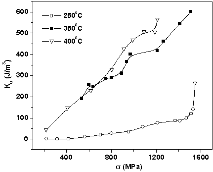
Figure 5.5: The development of a uniaxial anisotropy for an amorphous Fe78Si9B13 ribbon as function of temperature time at different annealing temperatures. Magnetic annealing field 400 kA/m. [Data taken from Thomas et al (1992)].


Growth and study of magnetostrictive FeSiBC thin films, for device applications, Mannan Ali (1999) 90
(Online Copy)


 Link bar
 Link bar

Email:Mannan.Ali@physics.org Chapter 5: Magnetic Anisotropy In Amorphous Films
Web: http://members.xoom.com/MannansZone/thesis.html


required time. It has been shown by Thomas et al (1992), that the magnitude of the anisotropy induced in Fe-based materials is dependent upon both the annealing time and the temperature. Figure 5.5 shows the results obtained from an FeSiB composition ribbon, where there is a clear trend shown with both temperature and annealing time.

Careful consideration is also needed when attempting to induce a uniaxial anisotropy in thin film sensors by the process of field annealing. The anisotropy induced by this method is relatively weak, and therefore the desired uniaxial domain structure may not be possible because of a significant contribution from the shape anisotropy due to the reduced lateral dimensions of the thin film sensors it will need to overcome.

In general, the field annealing is carried out under a low vacuum, usually in a wire-wound furnace arrangement similar to that used in this study (Fig. 3.9). However, in the case of amorphous wires, a circumferential anisotropy can be induced by current-annealing the samples using either DC or AC current [Costa-Kramer et al (1995), Dominguez et al (1996)] which optimises the magnetic anisotropy for magneto impedance effects (see MI). Current annealing has also been used to induce a transverse uniaxial anisotropies in ribbon materials [Valenzuela et al (1997)].

5.6.2 Stress Annealing

Up to the present time, the effects of external stress on the magnetic properties of materials have been mainly investigated on wires or ribbons [Spano et al (1982)], since it is a relatively straight-forward procedure to apply a tensile stress to such materials. For the same reasons stress annealing at high temperatures to induce a magnetic anisotropy has therefore also been confined to these bulk materials [Ref. List (5.2)]. The technique of stress annealing relies on the inverse magnetostrictive effect, where the magnetisation couples with the applied stress, and therefore the effect is more pronounced in highly magnetostrictive materials. The magnetic sample is placed under a tensile stress and annealed at a temperature below the crystallisation temperature so that the initially stressed sample becomes the zero stress state. On removal of the of the external tensile stress after the annealing, the sample is placed in a

development of a uniaxial anisotropy

Figure 5.6: The development of a uniaxial anisotropy for an amorphous Fe3Co67Cr3Si15B12 ribbon as function of applied stress by the process of stress annealing at different annealing temperatures. Annealing time 1 hour. [Data taken from Dmitrieva et al (1999)].


Growth and study of magnetostrictive FeSiBC thin films, for device applications, Mannan Ali (1999) 91
(Online Copy)


 Link bar
 Link bar

Email:Mannan.Ali@physics.org Chapter 5: Magnetic Anisotropy In Amorphous Films
Web: http://members.xoom.com/MannansZone/thesis.html


state of compressive stress. Depending upon the sign of the magnetostriction of the material, a uniaxial magnetoelastic anisotropy will develop, either parallel or perpendicular to the stress axis. In the case of amorphous wires it is possible to use stress annealing to induce a circumferential anisotropy [Panina et al (1996), Sanchez et al (1996)]. This technique of stress annealing has been extended and applied to amorphous FeSiBC thin films deposited onto relatively ridged substrates [Ali et al (1999,1998)] and is discussed later in this chapter.

Investigations of stress annealing on ribbon samples have shown that the magnitude of the uniaxial anisotropy induced is dependent upon both the temperature and magnitude of the stress applied, and is also reversible; annealing the sample in the absence of any stress reduces the magnitude of the induced anisotropy [Dmitrieva et al (1999)]. The dependence of temperature on stress annealing is shown in Figure 5.6. As one would expect, increasing the annealing temperature accelerates the diffusion process forming a magnetic anisotropy at higher rate for the same annealing period. As with magnetic annealing, it important that the sample is stress relieved, and therefore the stress annealing is carried out at the same annealing temperatures used to stress relieve the sample.

5.6.3 Annealing

The inhomogeneous stresses which are present in films or ribbons have the effect of degrading the magnetic properties of the material, as discussed in the preceding chapter, and therefore a stress relief is usually implemented to relieve these stresses which are carried out at temperatures below the crystallisation temperature. Annealing of a sample also generally has the effect of reducing the induced magnetic anisotropies outlined above.

5.7 Domains in thin films

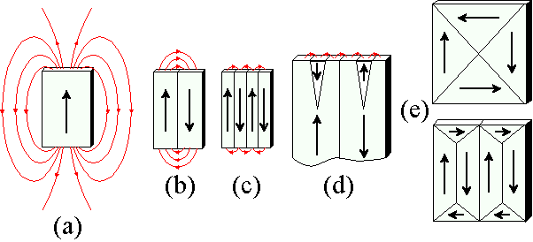
In the absence of any magnetocrystalline anisotropy, the magnetisation will lie in the plane of film because of the large shape anisotropy. There would be no preferred direction for the magnetisation in the plane of the film (assuming Nd=1) if no other form of anisotropy was present. However, it is found that films do possess domain structures which are nucleated in order primarily to reduce the magnetostatic energy which is associated with the stray field emanating from the magnetic sample. The domain and domain wall structure in magnetic films are dependent on the minimisation of the total energy of the system which include the anisotropy, exchange, magnetostatic, magnetoelastic and domain wall energies. The effect of the magnetostatic energy is illustrated in Figure 5.7, where the stray field from a uniformly magnetised sample which has a uniaxial anisotropy is shown. In the single domain configuration, there are a large number of free "magnetic poles" at the ends of the film which gives rise to a large stray field or magnetostatic energy. This energy is approximately halved if the single domain splits into two domains which are oppositely magnetised as shown in Figure 5.7b. In this case the opposite "magnetic poles" are now closer in proximity to each other, decreasing the amount of stray field emerging from the sample. Subsequent sub-divisions of the domains as shown in Figure 5.7c


Growth and study of magnetostrictive FeSiBC thin films, for device applications, Mannan Ali (1999) 92
(Online Copy)


 Link bar
 Link bar

Email:Mannan.Ali@physics.org Chapter 5: Magnetic Anisotropy In Amorphous Films
Web: http://members.xoom.com/MannansZone/thesis.html


Stray magnetic field

Figure 5.7: Illustration of stray magnetic field from a sample with a uniaxial anisotropy with (a) single magnetised domain, (b) two and (c) four domains. (d) Reverse spike domains which can form in a uniaxial domain structure. (e) Flux closure domains which prevent any stray flux from emerging from the sample.

will result in further reductions in the magnetostatic energy. The sub-division of the domains continues until the energy needed to create a new domain wall exceeds the accompanying reduction in the magnetostatic energy. Often a material with a uniaxial anisotropy will form reverse spike domains (Fig. 5.7d) at the edges of the film to introduce "magnetic poles" of the opposite sign at the edges of the film reducing the magnetostatic energy; this occurs without a significant increase in the domain wall energy because of their short length. The domain walls shown in Figures 5.7a-d, are known as 1800 walls, since the magnetisation on either side of the wall is anti-parallel, and they occur in virtually all materials. Examples of 900 walls are shown in Figure 5.7e, where the magnetisation direction changes by 900. In these two examples, there are no free poles and therefore the magnetostatic energy is reduced to zero. These types of domain structures tend to occur in cubic crystals where there are easy axes at 900 to each other. These triangular domains are known as closure domains. It is usual that the second type of domain structure containing both 1800 and 900 walls is formed, since it reduces the magnetoelastic energy which is dependent upon the area of the domains. For example, if the magnetostriction of the material is positive, then all domains will distort in the direction of the domain magnetisation. In the case of the domain structures shown in Figure 5.7e this is prevented by the adjoining domains, which therefore introduce strain into the domains. Closure domains tend not to form in films with a uniaxial anisotropy since it involves the magnetisation pointing along a hard axis which is energetically unfavourable. If the anisotropy Ku induced is relatively small, then closure domains have known to be formed to reduce the magnetostatic energy. One should refer to the text of Hubert et al (1998), where a vast range of domain structures possible in thin films have been presented. It should be noted that when a film is magnetically saturated along an easy axis, the film can still remain as a single domain on removal of the magnetic field. This is due to the in-plane demagnetising fields being essentially zero, especially if the film is relatively large.

The domain walls in films extend through the entire thickness of the film as shown in Figure 2.27e where domain images were taken from the top and bottom surface of an FeSiBC thin film deposited in this study. Domain walls have a finite width where the magnetisation rotates gradually from one domain


Growth and study of magnetostrictive FeSiBC thin films, for device applications, Mannan Ali (1999) 93
(Online Copy)


 Link bar
 Link bar

Email:Mannan.Ali@physics.org Chapter 5: Magnetic Anisotropy In Amorphous Films
Web: http://members.xoom.com/MannansZone/thesis.html


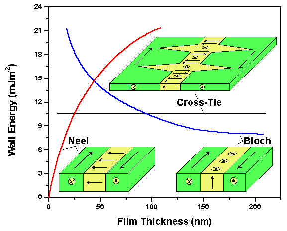
direction to the other. The width of a domain wall is dependent upon the exchange energy which prefers the magnetisation to rotate slowly from one orientation to the other leading to wide walls, whereas the anisotropy and demagnetising energies prefer the magnetisation to switch instantly to the opposite direction and therefore prefer narrow walls. An equilibrium between these energies determines the thickness of the domain wall. There are three main types of domain walls which can exist in thin films; these are illustrated in Figure 5.8. The Bloch wall is the same type of wall which appear in bulk materials were the magnetisation rotates out of the plane of the film. A Néel wall is defined by the magnetisation rotating in the plane of the film which reduces the magnetostatic energy of the wall, since the magnetisation is not pointing in an unfavourable directions (out of plane) as with a Bloch wall. A cross-tie wall is defined by a mixture of spins pointing out and in the plane and is identifiable by spike walls which form to ensure flux closure. It is found that in thin films Néel walls have a lower magnetostatic energy than Bloch walls and are therefore more energetically favourable. The energies of different types of walls in thin films are shown in Figure 5.8 as a function of film thickness for a permalloy film. The cross-tie walls appear in between the transition region from Bloch to Néel walls. The widths of the domain walls also vary as a function of film thickness where Bloch walls become narrower and Néel walls become wider with decreasing film thickness.

Knowledge of the domain structure enables a better understanding of the magnetisation and hysteresis process in ferromagnetic materials. On application of an applied field, the domains whose magnetisations are closest to the direction of the applied field will grow at the expense of domains which are not. For example, if a magnetic field is applied vertically along the domain structure shown in Figure 5.7b, the magnetisation process will occur purely by domain wall displacement. However, if a

Comparison of domain wall energies

Figure 5.8: Comparison of domain wall energies for a Bloch, Néel and Cross-tie wall for a permalloy film as function of film thickness [Data obtained from Prutton (1964)] and illustrative diagrams of the respective domain wall spin configuration.


Growth and study of magnetostrictive FeSiBC thin films, for device applications, Mannan Ali (1999) 94
(Online Copy)


 Link bar
 Link bar

Email:Mannan.Ali@physics.org Chapter 5: Magnetic Anisotropy In Amorphous Films
Web: http://members.xoom.com/MannansZone/thesis.html


small field is applied to the domain structure shown in Figure 5.7e, the domains with the magnetisation parallel with the field will either grow or shrink respectively until there is only one domain with its magnetisation directed along the field and the unfavourable domains where the magnetisation is at 900. On further increases in the field, the magnetisation process will now occur by domain rotation, where the magnetisation in the unfavourable domains are rotated into the field direction until all the domains are swept out. Usually the magnetisation process is due to both domain wall motion and magnetisation rotation, unless the field is applied either parallel or perpendicular to a material which has a well defined uniaxial anisotropy. In general for sensors, it is preferred that the material possess a uniaxial anisotropy.

In stress sensor applications, for example, a change in magnetic permeability, m, is measured [Arai et al (1994)] as a function of the applied strain, e. In such cases, the effectiveness of the stress sensor is compared by determining a figure of merit (FOM) of the material, which can be defined as

Eq. (5.18)(5.18)

Since the permeability is inversely related to the anisotropy field, the FOM may be maximised by careful control over the direction and magnitude of the anisotropy. For maximum sensitivity, a sufficient anisotropy is required to properly define the easy and hard axes, but not to be so large that the relative change in permeability is severely reduced. The maximum FOM obtained for magnetostrictive materials is two orders of magnitude greater than the equivalent FOM for competing piezoresistive materials [Gibbs et al (1997)]; this indicates the potential for excellent highly sensitive devices.


Growth and study of magnetostrictive FeSiBC thin films, for device applications, Mannan Ali (1999) 95
(Online Copy)


 Link bar
 Link bar

Email:Mannan.Ali@physics.org Chapter 5: Magnetic Anisotropy In Amorphous Films
Web: http://members.xoom.com/MannansZone/thesis.html


5.8 Results and discussions

5.8.1 Radial Magnetic anisotropy of the as-deposited films

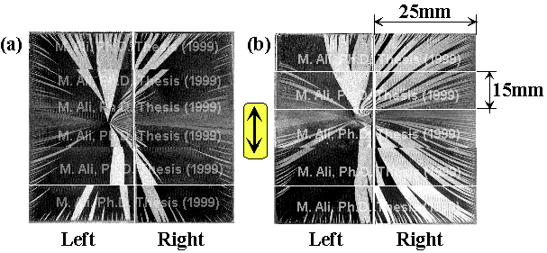
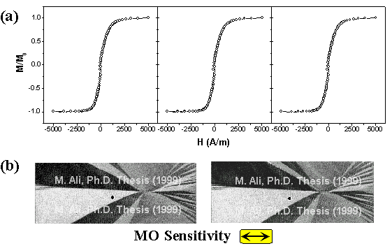
The as-deposited films display a significant, reproducible anisotropy which is radial about a central point corresponding to the centre of the magnetron sputtering source housing the target [Ali et al (1998)]. Figure 5.9 shows typical domain images obtained from films deposited on two standard (76mm´25mm) substrates which were deposited simultaneously at the optimised sputtering parameters; this figure shows the radially magnetic anisotropy where the easy axis of magnetisation is orientated radially from a central point on the left film. It is generally found that the anisotropy of the as-deposited films is uniaxial, but in this case (Fig. 5.9) it is shown that the induced anisotropy is radial in form when depositing films on large substrates. One should notice that the domains are not exactly continuous in Figure 5.9; the reason for this is, that it was only possible to obtain domain images up to an area of 25´15mm unless otherwise stated, and therefore the domain images shown across larger film surfaces are composite images constructed from individual images taken from the respective areas of the film. An important point emerging from these composite images is that the magnetisation process is reasonably reproducible, since the film had to be physically moved each time a different section of it had be imaged. This also meant the film had to be magnetically saturated and demagnetised each time in order to obtain a difference image (see MOKE Chapter). The domain images shown in Figure 5.9a,b are continuous in direction from the right to left film, and converge to a central point on the left film. The reproducibility of the magnetisation process was also confirmed by MOKE measurements, where

Typical domain images from as-deposited FeSiBC films

Figure 5.9: Typical domain images from as-deposited FeSiBC films displaying a radial induced magnetic anisotropy. The domain images are constructed from composite images (see text), where each image is 25x15mm in dimension. Note the dimension of one slide is 76´25mm. The images were obtained after the film was demagnetised along the length of the film. (a) An FeSiBC film deposited onto two glass slides. (b) An FeSiBC film deposited onto Corning® glass slides. See Figure 5.12, for a further example of the this radial induced magnetic anisotropy. The two films deposited in each growth will be referred to as the left and right films respectively in this study. (Transverse MO sensitivity), (75W,4mTorr).


Growth and study of magnetostrictive FeSiBC thin films, for device applications, Mannan Ali (1999) 96
(Online Copy)


 Link bar
 Link bar

Email:Mannan.Ali@physics.org Chapter 5: Magnetic Anisotropy In Amorphous Films
Web: http://members.xoom.com/MannansZone/thesis.html


repeated loops were taken from the same point. The MOKE loops are shown in Figure 5.10 where the loops cannot be distinguished. Domain images have also been included to indicate the reproducibility of the domains and the position at which the loops were taken.

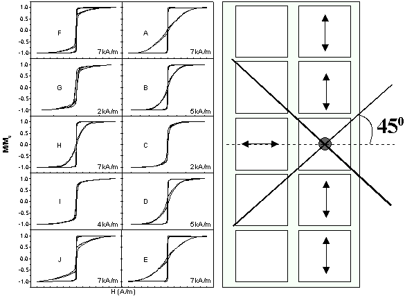
In the early stages of this study it was found that, in the case of the films which were deposited onto 1cm2 substrates, the magnitude and direction of the anisotropy was influenced by the positioning of the substrate on the substrate platter. The anisotropy of the films appeared to be isotropic in films which

MOKE loops

Figure 5.10: (a) MOKE loops of an as-deposited film indicating the reproducibility of magnetisation process. Loops taken vertically where the black circular spot indicates the position at which the loops were taken (b) Domain images taken from the central region of the left film. In each case the film was magnetically saturated and the image was taken with an applied field of 35A/m in the vertical direction.

Orthogonal MH loops

Figure 5.11: Orthogonal MH loops obtained from 1cm2 FeSiBC films which were arranged in the position of the left film. Hysteresis loops from film C, correspond to the sample which is directly above the target and is also indicated by the circular spot. The arrows in the diagram indicate the easy axis as determined from the MH hysteresis loops. The magnitude of the field at which the hysteresis loops were take are shown at the bottom right corner. (75W, 4mTorr).


Growth and study of magnetostrictive FeSiBC thin films, for device applications, Mannan Ali (1999) 97
(Online Copy)


 Link bar
 Link bar

Email:Mannan.Ali@physics.org Chapter 5: Magnetic Anisotropy In Amorphous Films
Web: http://members.xoom.com/MannansZone/thesis.html


were located directly above the centre of the target and at positions which lay along a line at 450 from the horizontal from position (c) as shown in Figure 5.11. In all other substrate locations, a uniaxial anisotropy appeared to develop in the films. The hysteresis loops were taken using the inductive magnetometer which only allowed measurements to be taken in two orthogonal directions parallel to the square edges of the substrates. This meant if the easy axis lay along a diagonal of the 1cm2 film, it would appear that the film was isotropic from the hysteresis measurements; this explains the significance of the films appearing isotropic along locations indicated by the solid lines projected at 450 from the horizontal from position (c). It was not until the MOKE magnetometer and MOKE imaging system were constructed (Chapter 2) that the magnetic anisotropy present in the as-deposited films was fully understood.

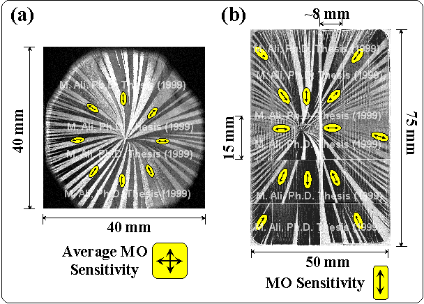
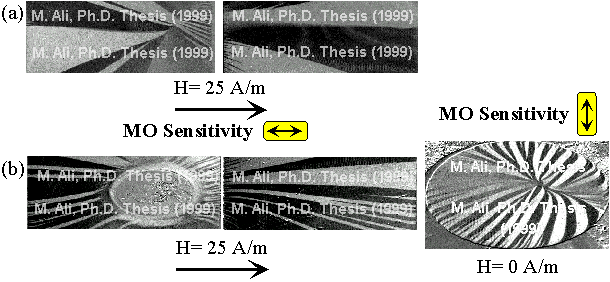
Films were deposited on substrates with dimensions of 76´50mm2 so that the magnetic anisotropy of the as-deposited films could be fully investigated without the complication of the centre of the radial pattern being effected by the edge of the film. Figure 5.12a shows the central region of the domain structure obtained from one such film. The easy axis was determined from both MOKE hysteresis measurements, which allowed the magnetic anisotropy to be investigated through a full 3600 in the plane of the film at any particular point (indicated by the arrows), and by observing domain growth on application of a magnetic field of known direction. It was found that the anisotropy appeared to be isotropic at the centre of the radial pattern, but was uniaxial as one moved away from the central point of the radial pattern in any direction, as also indicated by the domain structure. It should be noted that the domain structure shown in Figure 5.12a is a demagnetised domain pattern obtained by combining images sensitive to the transverse and longitudinal components of the magnetisation (see MOKE

Radial domain structures

Figure 5.12: Radial domain structures from a FeSiBC film deposited on silicon. (a) Domain image from central region of film (b) Domain image from the same film, but with film cut into narrow strips. Note (b) is a composite image of the entire film. The arrows in the two images indicate the direction of the easy axis as determined from MOKE measurements. (75W, 4mTorr)


Growth and study of magnetostrictive FeSiBC thin films, for device applications, Mannan Ali (1999) 98
(Online Copy)


 Link bar
 Link bar

Email:Mannan.Ali@physics.org Chapter 5: Magnetic Anisotropy In Amorphous Films
Web: http://members.xoom.com/MannansZone/thesis.html


Chapter). The domain image is very symmetric about the central point and reverse spike domains exist at the edges of the film so as to reduce the magnetostatic energy. The demagnetised domain structure of the same film is shown in Figure 5.12b, where the film had been cut into narrow strips, and the entire film was imaged. This domain image demonstrates that the anisotropy is, indeed, radial in form, since the domains on the individual film strips still converge to the same central point on the left, even though the strips were not in physical contact with one another and hence no magnetic coupling existed. Clearly, a uniaxial domain structure exists on a local scale across the width of the outermost strips, which slowly rotates along the length of the film strips in accordance with the radial anisotropy, whereas the uniaxial anisotropy of the central strips is aligned approximately along the length of the films. MOKE measurements, indicated by the arrows, also confirm the direction of the anisotropy as shown by the domain structure. Further examples of domain images illustrating the radial anisotropy can be seen in Figure 5.34, obtained from patterned films.

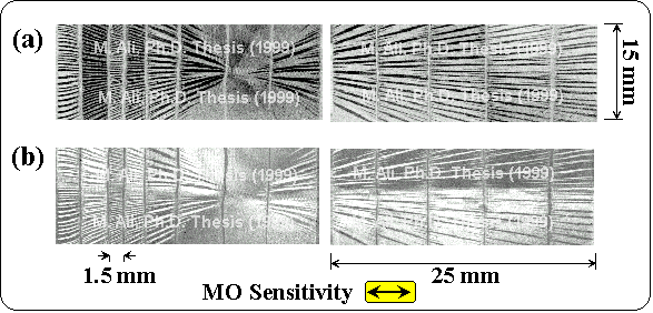
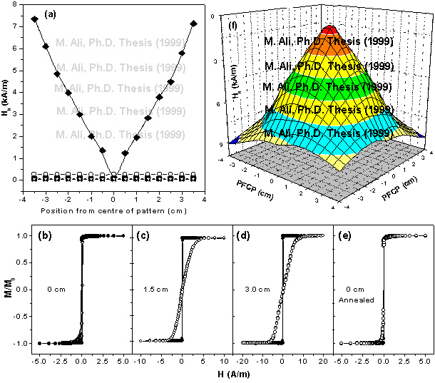
The breaking up of the complete film does not affect the radial anisotropy and a further example of this is shown in Figure 5.13, where domain images were obtained from the central region of the narrow films strips in their remanent state after being magnetically saturated along the length and width of the film respectively. The anisotropy induced in the films is sufficiently large and well defined that the domain structure reverts back to the form dictated by the radial anisotropy. The anisotropy is unaffected by the width of the film strips even for the film strip which has a shape aspect ratio of 50:1, but there is an increase in the density of domains per unit area for the narrower films in order to reduce the magnetostatic energy; this behaviour is as one would expect. The magnitude of the uniaxial anisotropy present in the film is found to increase as a function of distance from the centre of the radial pattern. The variation of the anisotropy field along a straight line through the centre of the radial pattern, as measured with MOKE, is shown in Figure 5.14a. At the centre of the pattern the anisotropy field is small and isotropic, but the anisotropy transforms into a well defined uniaxial anisotropy as one moves away from the centre of the pattern with its magnitude increasing linearly. Examples of easy and hard axis loops are shown in Figures 5.14(b,c,d) which indicate a uniaxial anisotropy. On annealing the film,

Radial domain image

Figure 5.13: Radial domain image obtained from the central region of a FeSiBC film which has been cut into various widths. Initial film deposited onto a silicon substrate 76´50 mm. (a) Remanent image after being magnetically saturated across the width of the film strips (b) Remanent image after being magnetically saturated along the length of the film strips. (75W, 4mTorr).


Growth and study of magnetostrictive FeSiBC thin films, for device applications, Mannan Ali (1999) 99
(Online Copy)


 Link bar
 Link bar

Email:Mannan.Ali@physics.org Chapter 5: Magnetic Anisotropy In Amorphous Films
Web: http://members.xoom.com/MannansZone/thesis.html


Variation of the anisotropy field

Figure 5.14: (a) The variation of the anisotropy field measured along straight line which passes through the centre of the radial domain pattern for a typical FeSiBC film. The solid diamonds represent the hard axis values and the solid squares are the easy axis values for an the as-deposited film. The open circles (hard axis) and the open stars (easy axis) are the respective values (orthogonal measurements) after the film has been annealed (3900C:1hour). (b),(c) and (d) are the MOKE hysteresis loops for positions indicated from the centre of the pattern. (e) are the loops from the film after being annealed from the location where the centre of the radial pattern existed. (f) represents a computed 3d map of the anisotropy field generated from six 2d-line scans as shown in (a) for the as deposited film.

it is found that the radial anisotropy is removed and the film displays no preferential anisotropy (Fig. 5.14e) but is uniform throughout (Fig. 5.14a); this is obviously very important for the mass production of sensors. It would not be economically viable if only one sensor could be coated at time because of the differing magnetic properties due to the position of the sensor on the substrate platter. Obviously, this radial anisotropy could also be utilised to control the direction of the anisotropy and the magnitude of anisotropy field induced in a number of sensors in the one deposition by the careful positioning of the substrates on the substrate platter; the anisotropy field is shown to increase linearly with distance from the centre of the pattern (Fig. 5.14a) and is radially symmetric about the centre as shown by the 3D map of the anisotropy field in Figure 5.14f. The sample or sensors would ideally need to be no larger than 1-2mm2 in order to ensure that the anisotropy was uniform over the whole film. It is important to be aware of such magnetic anisotropies which can result from sputter deposition, especially in the growth of soft magnetic materials over large areas.


Growth and study of magnetostrictive FeSiBC thin films, for device applications, Mannan Ali (1999) 100
(Online Copy)


 Link bar
 Link bar

Email:Mannan.Ali@physics.org Chapter 5: Magnetic Anisotropy In Amorphous Films
Web: http://members.xoom.com/MannansZone/thesis.html


Domain images taken under the influence of an applied field.

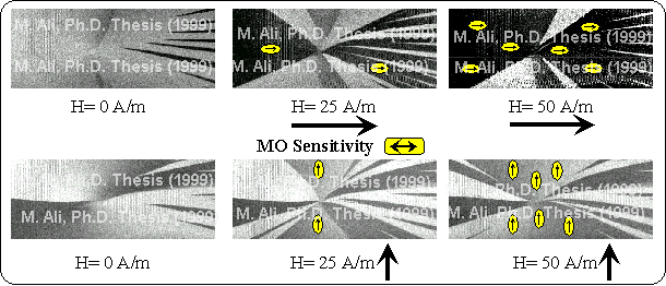
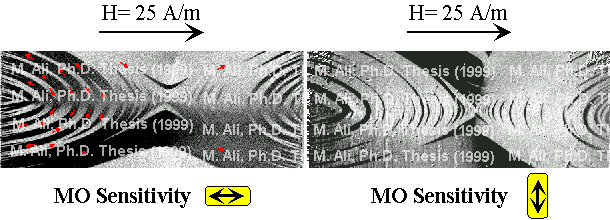
Figure 5.15: Domain images taken under the influence of an applied field. The two fields used were orthogonal to each other. (75W, 4mTorr).

Figure 5.15 are domain images taken of the central region of the radial pattern at the applied fields shown. The film was initially saturated in the opposite direction to the applied fields shown in the two sets of images. The application of an applied field in the horizontal or vertical directions illustrates the radial anisotropy present by the growth of favourable domains in the direction of the applied field at the expense of the unfavourable domains. At remanence, the film is not a single domain and some domain structure is present to reduce the magnetic energy of the system. It should be noted that not all the domain structure is visible here, since the MO sensitivity in these images is dependent upon the longitudinal component of the magnetisation. On the images the growth of the favourable domains is illustrated by the arrows. On the onset of an applied field in either direction, the nucleated domains converge to the central point and the favourable domains grow in size at the expense of the others. The reason for the domains to converge to this central point is the strength of the anisotropy and its radial form, which can be clearly seen in Figure 5.14f. The magnitude of the anisotropy is symmetric and decreases radially to a minimum at the central point. Hence, the application of a field in any direction in the plane of the film will always nucleate a domain, which will be parallel to the field and also pass through this central point, since the applied field will always point along an easy axis of magnetisation through this central point as shown by the demagnetised domain image of Figure 5.11a. Domain structures in which the magnetisation points in a non-easy axis will not form at the low fields because of the large anisotropy energy required. Instead, the domains initially converge to this central point in accordance with the radial anisotropy and the applied field to minimise the magnetic energy of the system. Domains with the same domain magnetisation join together at this point, as can be seen from the two sets of images. Since the anisotropy is a minimum at this point, the favourable domains grow in size sweeping radially from this point. At higher fields, the magnetisation process proceeds with both domain wall movement and domain rotation.


Growth and study of magnetostrictive FeSiBC thin films, for device applications, Mannan Ali (1999) 101
(Online Copy)


 Link bar
 Link bar

Email:Mannan.Ali@physics.org Chapter 5: Magnetic Anisotropy In Amorphous Films
Web: http://members.xoom.com/MannansZone/thesis.html


Thickness profile

Figure 5.16: (a) Computed 3d map of the thickness profile across a FeSiBC film from 2d thickness line scans. PCPP=Position From Centre of Pattern. (75w, 4mTorr, 2mm). (b) A schematic diagram of expected domain structure from such thickness profile.

Ferromagnetism only appears when the sputtered atoms deposit themselves on the substrate, therefore it was believed that this spot on the left film corresponded to the thickest part of the film which would also be the first point where any ferromagnetism would appear. The reminder of the depositing film was then assumed to be influenced by this thus point giving rise to this unique radial anisotropy. A three dimensional thickness map was computed from two dimensional line scans of the thickness profiles (Fig. 3.6) to ascertain the thickest part of the deposited film and the findings for a 2mm film are shown in Figure 5.16a. There is a well defined thickness profile, as one wound expect, where the thickest part of the film corresponded to the centre of the magnetron source and the radial spot. However, the magnetic anisotropy from such a thickness profile would not give rise to a radial anisotropy but to an anisotropy which is concentric in form as shown schematically in Figure 5.16b due the shape anisotropy.

Similar radial domain structures can also occur in films which are slowly cooled through their Curie point [Bishop (1998)]; however, this possibility was excluded since it was established that the temperature of the depositing film did not rise above 1000C.

Stress was also considered as a possible source of this anisotropy, because of the mounting of the substrates to the substrate platter. This possibility was eliminated by the use of a picture frame holder, which ensured that the substrates were free to move within the holder, and were only held in position under their own weight. It would be difficult to imagine that such a clamping procedure could repeatedly induce a spherically symmetric bending of the substrate, especially in the instances where two separate substrates were mounted. Stress could also be introduced because of the different thermal expansion coefficients of the substrate and the depositing film. However, it was found that simultaneous growth onto two separate substrates always produced a single spot in the radial anisotropy distribution, which always appeared on the left film corresponding to the centre of the target; the domain patterns were continuous from the right to the left film where they converged as shown in the Figures. Since the thermal contact between the two slides is very poor, this observation is inconsistent with the thermal mis-match or any thermal gradients which may exist across the two slides and thus being the cause of this radial anisotropy. Another source of stress from which the deposited films can suffer is the growth


Growth and study of magnetostrictive FeSiBC thin films, for device applications, Mannan Ali (1999) 102
(Online Copy)


 Link bar
 Link bar

Email:Mannan.Ali@physics.org Chapter 5: Magnetic Anisotropy In Amorphous Films
Web: http://members.xoom.com/MannansZone/thesis.html


Domain images

Figure 5.17: (a) Domain images taken from the left and right films which were separated by a distance of 5mm and lifted off the substrate platter to ensure isolation of the films during the deposition. Image dimensions 25´15 mm. (b) Domain images from films which were deposited with a cover slip over the central point of the pattern.

induced stress from the sputtering process as described earlier. However, in order to minimise this effect the growth conditions have been optimised as investigated in the previous chapter. It is difficult to imagine how the growth induced stresses would be so symmetrical about the same central point and also increase in strength radially from a central point so as to give rise to such a well defined anisotropy distribution as shown in Figure 5.14. Whilst stress free films are difficult to achieve, it is believed (see below) that another anisotropy mechanism dominates.

The above effects also cannot explain why the domain structure of the films deposited onto isolated substrates still display domains which converge to the central point directly above the target (Fig. 5.17a). The substrates were separated and lifted slightly from the substrate platter; this was to ensure that there was no magnetic coupling between the films through the material which was being deposited on the substrate platter, which could give rise to the continuous domains across the films due to the magnetic coupling. Films were also deposited simultaneously onto circular cover slips which were mounted directly over this central point. This was to ascertain whether the centre of the pattern would be effected and move to a new position. The cover slip was mounted in such away that there was no magnetic coupling present between the depositing film on the cover slip and the depositing films on the two glass slides. It is can be seen from Figure 5.17b that the radial anisotropy is still present, the centre of the pattern has not moved and is visible on the cover slip. The anisotropy mechanism which is inducing this radial anisotropy is able to exert its influence in films which are not physically connected to each other. As discussed previously, the morphology of a depositing film can induce a contribution to the anisotropy. Under certain conditions columnar growth, caused by the self shadowing of the depositing atoms can also give rise to an in-plane anisotropy. It has been shown by Leamy et al (1979) that incident atoms arriving at oblique angles to the substrate, will form a film with a columnar structure which is at an oblique angle governed by equation 5.17. This type of columnar growth could explain the radial anisotropy and why the domains appear continuous on isolated substrates, but it is very unlikely that such an effect could produce incident atoms with a radial distribution and an increasing angle of


Growth and study of magnetostrictive FeSiBC thin films, for device applications, Mannan Ali (1999) 103
(Online Copy)


 Link bar
 Link bar

Email:Mannan.Ali@physics.org Chapter 5: Magnetic Anisotropy In Amorphous Films
Web: http://members.xoom.com/MannansZone/thesis.html


Magnetic field pattern

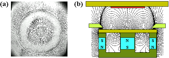
Figure 5.18: (a) Magnetic field pattern obtained from the residual magnetron field present at the substrate platter using iron filings from target position one. (b) Schematic illustration of the magnetic field pattern between the target and substrate platter.

incidence as a function distance from the centre. Generally, it is found that the columnar structure induces a uniaxial anisotropy in the films. However, the deposition geometry (15cm diameter target) used in this study and the optimised sputtering parameters at which the film were deposited, preclude such an explanation.

The effects of a forming field during the deposition of magnetic films is a well known method of inducing a uniaxial anisotropy. In this study it was found that a weak residual field from the magnetron source was present at the substrate platter during the deposition of the films; this had a radial symmetry about the centre of the magnetron source. This radial symmetry is shown in Figure 5.18a, where the magnetic field pattern was obtained using iron filings. Figure 5.18b is schematic diagram of the shape of the magnetic field pattern which is likely to be present between the target and substrate platter as a result of the magnetron. The strength of this field at the substrate platter was found to be approximately 500 A/m with the target configuration shown in Figure 3.3. From Figure 5.18a it is apparent that the FeCo backing plate and the METGLAS® 2605SC ribbon target were not flux closing all the magnetron field, and there was, therefore, a component of the residual field parallel to the substrate platter. The radial anisotropy present in the as-deposited films was therefore attributed to the variation of the in-plane component of this residual field from the magnetron source. This was further verified by placing weak permanent magnets on either side of the substrates to show that the radial anisotropy could be modified by an additional magnetic field. As discussed earlier, introducing strong magnetic fields near the substrate will dramatically effect the dynamics of the sputtering process, and would therefore have required optimising the sputtering parameters to account for this. However, the radial anisotropy being investigated could have also been effected by these changes in the sputtering parameters. The current system was not designed for housing permanent magnets at the substrate platter, and considerable modifications would have been required to house the magnets ideally, as shown for example in Figure 5.4. This problem was overcome by the use of very weak, flat, bar magnets which produced a measured magnetic field of approximately 800 A/m. The strength of the field is comparable with that of the residual field from the magnetron source and therefore had little influence on the dynamics of the sputtering process occurring at the substrate. Pieces of the METGLAS® 2605SC ribbon were cut to size and bonded to the top side of the bar magnets which were facing the plasma. This prevented the plasma from actually coming into contact with the magnets, and it also flux closed any magnetic field lines


Growth and study of magnetostrictive FeSiBC thin films, for device applications, Mannan Ali (1999) 104
(Online Copy)


 Link bar
 Link bar

Email:Mannan.Ali@physics.org Chapter 5: Magnetic Anisotropy In Amorphous Films
Web: http://members.xoom.com/MannansZone/thesis.html


Film which was deposited using a forming field

Figure 5.19: Domain images taken from an FeSiBC film which was deposited using a forming field provided by two weak bar magnets.

Variation of the anisotropy field

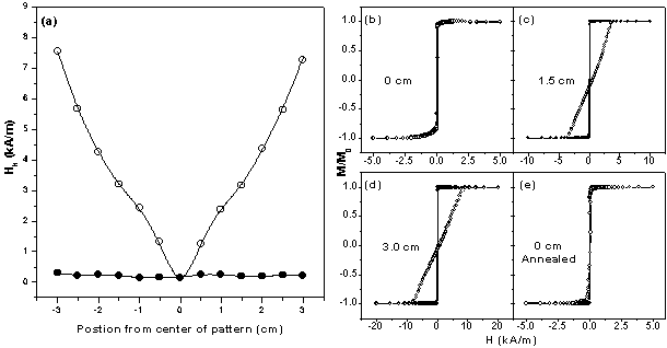
Figure 5.20: (a) The variation of the anisotropy field as measured along straight a line which passes through the centre of the radial domain pattern for a FeSiBC film which was deposited in the absence of an FeCo backing plate. The open circles represent the hard axis values and the solid circles are the values after the film has been annealed (3900C:1hour). (b),(c) and (d) are the MOKE hysteresis loops for positions indicated from the centre of the pattern. (e) are the loops from the film after being annealed from the centre.

emanating into the plasma. It was found that the positioning of the bar magnets around the substrate did, indeed, modify the radial anisotropy, and one of the more interesting anisotropies induced is shown in Figure 5.19. Here two bar magnets were placed on either side of a glass substrate such that the magnetic field lines from the two magnets parallel to the substrate surface were semi-circular in form. The domain images indicate vividly the form of these magnetic field lines by the presence of semi-circular domains; the domain directions have been indicated by the small arrows. The magnetic softness of the films deposited in the presence of these bar magnets showed no deviations from the standard films which were deposited.

Having ascertained that the radial anisotropy in the films was due to the residual field from the magnetron source, films were deposited in the absence of the FeCo backing plate; this increased the horizontal component of the residual field at the substrate platter to approximately 1kA/m. The magnetic field pattern at the substrate platter obtained by iron filings had a similar appearance to that of Figure 5.18a. The removal of the FeCo plate halved the deposition rate, so the growth time was doubled


Growth and study of magnetostrictive FeSiBC thin films, for device applications, Mannan Ali (1999) 105
(Online Copy)


 Link bar
 Link bar

Email:Mannan.Ali@physics.org Chapter 5: Magnetic Anisotropy In Amorphous Films
Web: http://members.xoom.com/MannansZone/thesis.html


so as to maintain the standard film thickness of 500nm. No difference in the magnetic softness was found and the radial anisotropy was still present as shown in Figure 5.20. The profile of the anisotropy field across the film was similar to that found in films deposited with the FeCo backing plate. In the more usual ribbon form of ferromagnets, the introduction of a uniaxial anisotropy by means of magnetic annealing is a well established technique, as demonstrated by Thomas et al (1991). The magnitude of the field strength necessary to achieve a well defined domain structure is of the order of 5x10⁴ A/m for amorphous ribbons; this is much larger than the stray residual field from the magnetron present at the substrate platter, but is similar to the field (200kA/m) used in this study to magnetically anneal the as-deposited FeSiBC films. This is a consequence of the kinetic energies of the impinging sputtered atoms as they adhere to the substrate. At the surface of the substrate the atoms are highly mobile, allowing the residual field to exert a significant influence. Consequently the directional ordering of like atom pairs is notably larger, whereas in ribbons or films a large field in conjunction with an annealing temperature of the order of the Curie temperature is necessary to provide sufficient mobility of the atoms. The reported [Thomas et al (1991)] hard axis anisotropy fields for METGLAS® 2605SC ribbon after optimal field annealing is approximately 100 A/m (Ku~80 Jm-3), whereas Figure 5.14 shows that Hk can vary from 150-8000 A/m using the residual forming field present at the platter. It is clear from these results that the introduction of an anisotropy with a forming field produces a well defined anisotropy at significantly lower fields.

It is important therefore to be aware of such anisotropies as can result from magnetron sputter deposition, especially where soft magnetic (300 A/m) materials are being deposited over large areas where the coercive fields of the depositing film are small in comparison with the residual field. By careful positioning of the small substrates on the substrate platter, one can control both the magnitude and direction of the induced uniaxial anisotropy. This is shown in Figure 5.21, where a well defined uniaxial anisotropy is obtained from two as-deposited films positioned 3.5cm and 7cm from the central spot. The film in Figure 5.21b was also rotated through 150 to illustrate that the uniaxial anisotropy can be induced at any direction in the film. The hard axis anisotropy fields induced in the two films were

Domain images and respective MOKE loops

Figure 5.21: Domain images and respective MOKE loops from as-deposited films. (a) The substrate was positioned 3.5 cm from the central spot along x-axis [Ali et al (1998)]. (b) The substrate was positioned 7 cm from the central spot and rotated though 150. The easy and hard axis are shown. Domain images taken at remanance (H=0 A/m).


Growth and study of magnetostrictive FeSiBC thin films, for device applications, Mannan Ali (1999) 106
(Online Copy)


 Link bar
 Link bar

Email:Mannan.Ali@physics.org Chapter 5: Magnetic Anisotropy In Amorphous Films
Web: http://members.xoom.com/MannansZone/thesis.html


Domain images

Figure 5.22: Domain image from a (a) 10nm and (b) 50nm as deposited FeSiBC film.

5kA/m and 15kA/m respectively, significantly larger than the process of field annealing.

The effects on the radial anisotropy of varying the pressure is as one would expect. That is, below about 4mTorr it is completely overcome by the more dominant stress-induced anisotropy, which gives rise to a perpendicular anisotropy. Above 4mTorr the coercivity increases slowly with pressure, and it is found that the radial anisotropy becomes less distinct with increasing pressure. The general findings were that if the as-deposited film had coercive fields larger than approximately 250A/m, then no radial domain structure was visible. No attempt was made to map the anisotropy profiles of these films as in shown Figure 5.14, since they would be of no practical use here because of the larger coercive fields. The domain images from a 10 and 50nm as-deposited film are shown in Figure 5.22, where the film was deposited at the optimised sputtering parameters. These images show that the radial anisotropy is no longer present and some other mechanism dominates. The easy axis coercive fields of theses two films were 286 and 311 A/m respectively.

Summarising, the radial anisotropy is due to the horizontal component of the residual field from the magnetron sputtering source. Any other anisotropy mechanism which has a larger influence than the residual field of approximately 500 A/m, will dominate and overcome this radial anisotropy. Annealing the samples without an applied field reduces both the coercive and anisotropy fields to ~10 and ~100 A/m, respectively. The radial anisotropy in the as-deposited films is destroyed (Fig. 5.14,5.20), and the domains sweep very rapidly through the entire film, making domain imaging very difficult. Small reverse spike domains are visible at the edges of the films. MOKE hysteresis loops have shown that a very weak easy axis lies along the length of the films.


Growth and study of magnetostrictive FeSiBC thin films, for device applications, Mannan Ali (1999) 107
(Online Copy)


 Link bar
 Link bar

Email:Mannan.Ali@physics.org Chapter 5: Magnetic Anisotropy In Amorphous Films
Web: http://members.xoom.com/MannansZone/thesis.html


5.8.2 Magnetic Annealing

It was found that magnetic annealing with an applied field perpendicular to the length of the films, introduced a weak transverse anisotropy. Typical result are shown in Figure 5.23, where both domain images and MOKE loops confirm that a uniaxial anisotropy has been induced. The domain images shown in Figures 23b,c are the corresponding images after the film was initially magnetically saturated along the hard and easy axis, respectively. Application of a small magnetic field of the order of the coercive field along the easy axis gives rise to a typical uniaxial domain structure where the domains are parallel to the easy axis. It should be noted that the film was a single domain at remanence (not shown) with small reverse spike domains present at its edges. The domain structure, which results from saturating the film along the hard axis, is typical of a film exhibiting anisotropy dispersion, where the easy axis and/or the magnitude of the uniaxial anisotropy constant, deviates slightly from place to place in the film. The domain structure is this case is still uniaxial and approximately parallel to the easy axis, but the domains are significantly narrower (~80mm-1mm) in comparison to the situation when the film was initially saturated along the easy axis (~3mm). It should be noted that the magnitude of the induced anisotropy field obtained by this treatment is significantly lower (~300 A/m) in comparison to what can be achieved by using a forming field, but sufficient to control the domain structure.

MOKE hysteresis loops

Figure 5.23: (a) MOKE hysteresis loops taken from the centre of the area shown. Solid and dashed lines indicate the magnetic field applied along the long and short axes of the sample respectively. The asymmetrical loop shape for the hard is reproducible, and is due to the use of a point probe of magnetisation in films in which domain wall movement is the dominant magnetisation mechanism and very fine domain structure exits. (b) Domain image of a field-annealed film with field applied along the easy axis after being magnetically saturated in the opposite direction. (c) Image obtained after field is applied along the hard direction. (15´25mm).


Growth and study of magnetostrictive FeSiBC thin films, for device applications, Mannan Ali (1999) 108
(Online Copy)


 Link bar
 Link bar

Email:Mannan.Ali@physics.org Chapter 5: Magnetic Anisotropy In Amorphous Films
Web: http://members.xoom.com/MannansZone/thesis.html


5.8.3 Magnetostriction and Magnetoelasticity

The introduction of a uniaxial anisotropy in soft, amorphous magnetic materials is conventionally achieved by the application of a suitable magnetic field, either during the growth process (a forming field) or during subsequent thermal treatment (field annealing) as described above.

An alternative, which is particularly suited to magnetostrictive thin films on flexible substrates, is to use stress [Ali et al (1999,1998)] itself to produce the required anisotropy. From the results and discussions up to this point it, is clear that stress can have a significant effect on the anisotropy. For the case of thin films, if the substrate is deliberately bowed during the deposition then, on release, it will return to its former shape, introducing stress into the film (note that the strain in the film will be opposite to the original substrate strain - if the substrate surface is held under tensile stress during the deposition then the film will be under compressive stress on release of the substrate). It is assumed that the mechanical properties of the film/substrate combination are dominated by those of the substrate. Another alternative is to flex the substrate during thermal processing such that the flexed substrate becomes the zero stress state of the film. The above treatments will be referred to as strained-growth and stress annealing respectively. These methods are assessed as novel alternatives to magnetic field treatments. A simple new technique is also described for the measurement of the saturation magnetostriction [Ali et al (1999] in amorphous thin films deposited on to rigid substrates; this is also based on mechanically introducing a small curvature in the substrate during or after the deposition.

Magnetostrictive materials in the form of thin films are becoming increasingly important for the development of sensors and actuators. Their incorporation into micro-electromechanical systems allows the production of a new range of devices which, unlike conventional piezoelectric and piezoresistive materials, can be remotely addressed and activated. In addition, these materials offer the possibility of self-test for safety-critical systems and also potential high sensitivity. It is therefore commercially and technologically important that one can investigate the magnetostriction constant of a material on a variety of substrates. Magnetostriction can be determined using either the magnetostrictive [Weber et al (1994)] or inverse magnetostrictive [Narita et al (1980)] effects. In the former case, the mechanical deflection of a cantilever system can be measured as the film magnetisation is rotated. The latter relies on measuring the induced change in anisotropy field as a mechanical stress is applied. The measurement of magnetostriction in thin film samples is not trivial. Techniques such as strain-modulated ferromagnetic resonance [Zuberek et al (1990)] (SM-FMR) and small angle magnetisation rotation [Narita et al (1980)] (SAMR) require thin, flexible substrates. Cantilever measurements can be made on thicker substrates [Klokholm (1976)], but there are difficulties in calibration and in the determination of absolute values of magnetostriction [Watts et al (1999)]. Magnetostriction is often investigated on flexible substrates in which a mechanical load can be applied to produce stress. However, in many cases, the magnetic properties of the films can vary dramatically with the substrate. It was found under certain instances, that thin films grown simultaneously on Corningâ glass and Kaptonâ (Polyimide substrate) had different magnetic properties. A further problem with measurement systems in which a


Growth and study of magnetostrictive FeSiBC thin films, for device applications, Mannan Ali (1999) 109
(Online Copy)


 Link bar
 Link bar

Email:Mannan.Ali@physics.org Chapter 5: Magnetic Anisotropy In Amorphous Films
Web: http://members.xoom.com/MannansZone/thesis.html


known load is applied, is in the calculation of the stress, particularly for the case of multilayer systems. In such cases, the stress in the magnetic layers is dependent on the structure. It is usually assumed that the strain is uniform throughout the thickness of the magnetic material.

Here, a novel new technique for measuring magnetostriction is described for thin films. It is based on mechanically introducing a small curvature into the substrate either during deposition (strained growth), thermal processing (stress annealing) or during the measurement, combined with the Magneto-Optical Kerr Effect (MOKE) to determine the stress induced anisotropy. Quantification of the stress in the magnetic layer gives the ability to determine accurately absolute values of magnetostriction. The technique described is based on a similar method which was first described by Becker and Kersten [Becker et al (1930)] and applied to nickel wires, and then by others to ribbon based materials [Ref. List (5.3)]. Similar methods have also been applied to thin films where the substrate\film are mechanically stressed. However the resulting stress induced anisotropy is obtained from magnetoresistive curves [Baril et al (1999), Markham et al (1989)] or from hysteresis loops obtained by the VSM [Han et al (1997)]. In both instances the magnetisation is monitored over a large area, where it is therefore essential that the strain is also uniform over this area.

Thin films differ from their bulk counterparts not only in their thickness, but also because of surface, substrate and possible texturing effects, which may influence the magnetic properties and hence the magnetostriction. It is therefore important that one should obtain the maximum magnetic information from such films in order to understand them fully.

5.8.3.1 Application of stress

An effective method of applying a controlled amount of stress to the FeSiBC films was to mechanically clamp the substrate/film over a knife edge at its two extreme points, as illustrated in Figure 5.24a. The strain in the film depends directly on the radius of curvature induced in the samples, which was determined by optical interferometry and stylus measurements. The optical measurement had the advantage of giving two dimensional information in a single measurement, whereas the stylus measurement gave a quick and accurate measurement of the curvature in a given direction. The results of the two techniques were found to be in good agreement and the stylus method was generally employed for convenience.

Figure 5.24b represents a region of the substrate/film which has been mechanically clamped over the knife edge, inducing a circular arc. The radius of curvature, R, was determined quickly and accurately from the stylus measurements from the variation of deflection, Y, with lateral position, X,:

Eq. (5.20)(5.20)

Substituting H=R-Y leads to


Growth and study of magnetostrictive FeSiBC thin films, for device applications, Mannan Ali (1999) 110
(Online Copy)


 Link bar
 Link bar

Email:Mannan.Ali@physics.org Chapter 5: Magnetic Anisotropy In Amorphous Films
Web: http://members.xoom.com/MannansZone/thesis.html


Eq. (5.21)(5.21)

A good approximation, when X>>Y, is that

Eq. (5.22)(5.22)

Assuming that the central element of the slide remains unstrained, the tensile strain in the top surface of the substrate is given by the following expression referring to labels shown in Figure 5.24b

Eq. (5.23)(5.23)
Eq. (5.24)(5.24)
Eq. (5.25)(5.25)

(R>>t, R>>F)

Eq. (5.26)(5.26)

Domain images and respective MOKE loops

Figure 5.24: (a) Schematic of the experimental method used for the introduction of mechanical strain into the film/substrate. (b) Illustrative profile of the radius of curvature from which the radius is calculated using a stylus method. Finite element model of a glass slide clamped tightly over a knife edge. The slide has dimensions of 76 mm x 26 mm x 0.4 mm. (c) and (d) show the magnitude of the strain in the top surface of the slide along the x and y axes respectively, (e) shows the deflection of the slide. [Ali et al (1999)].


Growth and study of magnetostrictive FeSiBC thin films, for device applications, Mannan Ali (1999) 111
(Online Copy)


 Link bar
 Link bar

Email:Mannan.Ali@physics.org Chapter 5: Magnetic Anisotropy In Amorphous Films
Web: http://members.xoom.com/MannansZone/thesis.html


where t is the thickness of the substrate; it is assumed that the thickness of the film is much smaller than that of the substrate which is generally the situation, and was always the case in this study. By this method, the strain is directly measured (on a local scale), and therefore no knowledge of the mechanical properties of the substrate was required as with other techniques simplifying the calculation.

It is realised that a beam or cantilever does not bend into a circular arc, and it has been shown [Joos (1958), Feynman (1964)] that the deflection (Y) is proportional to the cube of the length (X3), and not to the square (X2) as for the circular arc (Fig. 5.24b). The strain induced by the clamping process was investigated by three methods: Newton’s rings, stylus measurements and numerically. The investigation/measurements of the radius of curvature carried out by the Newton’s rings and stylus measurements revealed that a circular arc existed over a small region of the substrate, above the knife edge. This is shown in Figure 5.25a, where a typical Newton’s rings interference pattern is shown for a substrate/film under a tensile strain of 707 ppm. Figure 5.25b is a plot of the square of the lateral position (X2) versus the deflection (Y); this indicates that the curve, indeed, is circular over a distance of 5 mm. The strain induced anisotropy was measured using MOKE, which had a laser spot size of ~100mm in diameter, and therefore the strain was constant within the sampling area of the laser. This ensured that the measured strain and also the strain induced anisotropy could be directly correlated. The substrates used in this study were found to produce a circular arc over a length scale which was always much greater than the diameter of the laser spot (~100 mm). Films which are deposited onto substrates such as Kapton®, which are too flexible or liable to distort may be studied in this way by first depositing a thin layer of Kapton on a rigid substrate upon which the magnetic film is then deposited. In techniques such as the Small Angle Magnetisation rotation (SAMR) it is assumed that the strain induced is uniform throughout the film. The strain in the film was also numerically modelled using the ANSYSâ finite element modelling package [Watts (1998)]. This showed that the strain was not constant over the entire slide, but could vary greatly between the central region above the knife edge, compared to the areas near the clamping ends. Figure 5.24c shows the variation of strain with position for the top surface of a glass slide clamped rigidly over such a knife edge. The strain can be seen to be almost uniaxial in the x-

Domain images and respective MOKE loops

Figure 5.25: (a) Newton’s ring interference pattern obtained from a glass substrate/film which has been mechanical strained. The image has been enlarged and the scale of the image is shown. The x-axis corresponds to the length, and the z axis is the width of the sample. The y-axis is perpendicular to the page which corresponds to the deflection. (b) The square of the lateral position (X2) is plotted against the deflection from which the radius of curvature is determined for the given image (R=X2/nl). [Ali et al (1999)].


Growth and study of magnetostrictive FeSiBC thin films, for device applications, Mannan Ali (1999) 112
(Online Copy)


 Link bar
 Link bar

Email:Mannan.Ali@physics.org Chapter 5: Magnetic Anisotropy In Amorphous Films
Web: http://members.xoom.com/MannansZone/thesis.html


direction over the majority of the area of the slide, but with some edge effects near the clamps and close to the edges on either side of the knife edge. Since the techniques used to measure both the mechanical strain (stylus and interferometric) and the magnetic anisotropy probe the local properties, it can be concluded that, provided the same area is measured in both cases, reliable results can be obtained.

An obvious solution would have been to mechanically clamp the substrate\film over a cylindrical mould as shown in Figure 5.28c. This would have ensured that the strain was uniform across the entire film. However, this would have limited the possible strains available on the range of moulds available. It would have also required the removal of the sample each time, and therefore introducing uncertainty into the exact positioning of the MOKE laser spot each time. This is important when the strain is varied during the measurement (see strain during measurement), since it removes the need to take account of the intrinsic anisotropy present. In situations where the direction and magnitude of the anisotropy varies from position to position, it is therefore important that the same area of the film is sampled each time.

Strain was introduced into the samples in three different ways: by straining the substrate during the deposition, stress annealing and during the measurement. In the first and second cases, the curved substrate becomes the zero strain state for the film. When the substrate is released, it returns elastically to its original flat shape, straining the film in the process. Inducing a strain during the measurement allows a range of strains to be introduced. Measuring the resulting variation of magnetic anisotropy allows the accurate calculation of the magnetostriction.

The saturation magnetostriction constant ls, is determined from the variation of the strain induced magnetic anisotropy field, Hk , with the applied stress, s, from equation (5.28) [Mattheis et al (1999),

Eq. (5.28)(5.28)
Eq. (5.29)(5.29)

Gudeman (1990)] where MS is the saturation magnetisation, e is the measured strain, Ym and nf are the Young’s modulus and Poisson’s ratio of the film, respectively. It should be noted that the factor (1+nf) was not included in the analysis in Ali et al (1999), and an erratum has been submitted. Application of stress along the x -axis will also introduce stress in the y and z directions because of the Poisson’s ratio of the film [Gehring et al (1999)].

The saturation magnetisation of the material used in this study was assumed to be the same as that of the melt-spun METGLASâ 2605SC ribbon which was used as the target material, with m 0Ms = 1.61 T [Allied Signal (1995)]. The stress calculated depended upon the Young’s modulus of the film. Unfortunately, such values were not readily available for such amorphous sputtered films and a value of 160 GPa [Allied Signal (1995)] was assumed as for the target ribbon. It should be noted that the strain state and structure of the ribbon and film are likely to be different, with the possibility of different mechanical properties. However, evidence from the deflection of FeSiBC thin film membranes under pressure indicate similar values [Karl et al (1999)]. In the present case, the uncertainty in the Young’s modulus gives a large systematic error (±40GPa) which is much greater than the random errors in the


Growth and study of magnetostrictive FeSiBC thin films, for device applications, Mannan Ali (1999) 113
(Online Copy)


 Link bar
 Link bar

Email:Mannan.Ali@physics.org Chapter 5: Magnetic Anisotropy In Amorphous Films
Web: http://members.xoom.com/MannansZone/thesis.html


Strained growth

Figure 5.26: Strained growth (a) MOKE loops obtained along the easy (solid line) and hard (open circles) axes of magnetisation for a sample deposited while the top surface of the substrate was held under a strain of 562 ppm. The inset shows loops taken in the same directions for an unstrained sample. Comparison gives a strain-induced anisotropy of 5863 A/m. (b) MOKE domain image at remanence and at a field of 70 A/m applied along the easy axis. [Ali et al (1999)].

measurement of strain and anisotropy. A value for the Poisson’s ratio was not available for FeSiBC films nor for the target material from which the films were deposited. It is, however, found that the values for Fe-based metals is approximately 0.3 for films or bulk materials and therefore a value of 0.3 for Fe80B20 ribbon [Kunzi (1983)] was used for FeSiBC films deposited in this study.

5.8.3.2 Strained growth

FeSiBC films were produced by straining the substrate during the deposition process, and releasing it afterwards to introduce a strain into the film. The substrate curvature was verified pre- and post-deposition by interferometric and stylus measurements. Such a technique could be used as a simple method for the introduction of a controlled, uniaxial anisotropy for device fabrication. The disadvantage of the strained growth technique is that the strain-induced anisotropy will be added to the intrinsic growth anisotropy which is radial in form in this study. However, since the anisotropy induced during the deposition was found to be constant, it could be subtracted to quantify the magnetostriction measurement. Figure 5.26 shows the hysteresis loops and domain images obtained from a film deposited onto a strained substrate. The hysteresis loops indicate that the film exhibits a well defined uniaxial anisotropy, with no observable opening of the hard axis loop. The domain images confirm the well defined uniaxial anisotropy, with 180° domain walls running parallel to the easy axis. Reverse domain spikes appear at the edges to reduce the demagnetising effect. Subtraction of the intrinsic anisotropy (shown in the inset) yields a magnetostriction constant of 39.5±7.5 ppm, in good agreement with the bulk data [Allied signal (1995)]. The error in this measurement is dominated by that of the Young’s modulus. Further films grown with varying strains gave similar values. Figure 5.27a shows the variation of the anisotropy field along the length of a typical strained-growth film as measured by MOKE. At the central region of the film the anisotropy is purely uniaxial as expected and the magnitude of the anisotropy decreases along the slide because of the decrease in the strain along the x-axis, as computed and shown in Figure 5.24c. During the deposition, the forming field which is the


Growth and study of magnetostrictive FeSiBC thin films, for device applications, Mannan Ali (1999) 114
(Online Copy)


 Link bar
 Link bar

Email:Mannan.Ali@physics.org Chapter 5: Magnetic Anisotropy In Amorphous Films
Web: http://members.xoom.com/MannansZone/thesis.html


Variation of the anisotropy field

Figure 5.27: (a) The variation of the anisotropy field measured for a strained-growth film which was held under a strain of 571 ppm. (b) The variation of the anisotropy field measured for a stress annealed film which was held under a strain of 507 ppm. Domain images were taken at H=0 A/m from the two ends and the central region of the films. Image dimensions 15´25mm.


MOKE loops and domain image

Figure 5.28: (a) MOKE hysteresis loops taken from the centre of the domain image in (b). Solid and dashed lines indicate the magnetic field applied along the long and short axes of the sample respectively. (b) Domain image of a sample grown on a strained substrate. On release of the tightly clamped substrate, the film is held under a compressive strain of approximately 675 ppm in the direction indicated. [Ali et al (1999)]. (c) schematic of alternative clamping arrangement to ensure a constant strain across a film.

cause of the radial anisotropy, is the dominate anisotropy since the mechanically strained substrate does not induce any strain in the film until the substrate is allowed to return to its original form. The strain induced anisotropy is a maximum at the centre of the film over the knife edge (assuming that the knife edge is positioned at the centre of the radial anisotropy), where it is found that the radially induced anisotropy in comparison is insignificant on removal of the film. Moving away from the central region, the strain induced anisotropy decreases as the radial anisotropy increases, and the two anisotropies combine to produce a resultant anisotropy which is shown by the domain images taken from the two ends of the film. This shows that the anisotropy is no longer uniaxial across the width of the film. The magnitude of the anisotropy induced in the FeSiBC films by this method of strained growth can be substantially larger than the anisotropy induced by field annealing. Although the bending which can be applied to the substrates is limited by the elastic limit of the substrate and film, it is sufficient to produce an anisotropy field of 8kA/m in the current experimental arrangement (Fig. 5.28a,b). From a commercial point of view, it would more attractive if the anisotropy field were linear across the entire substrate. This could be achieved by clamping the substrate over a cylindrical mould (Fig. 5.28c) of the required radius so as to induce a constant anisotropy field, instead of a knife edge as used in this study.


Growth and study of magnetostrictive FeSiBC thin films, for device applications, Mannan Ali (1999) 115
(Online Copy)


 Link bar
 Link bar

Email:Mannan.Ali@physics.org Chapter 5: Magnetic Anisotropy In Amorphous Films
Web: http://members.xoom.com/MannansZone/thesis.html


This would ensure that the radius of curvature were constant along the entire substrate, giving rise to a constant anisotropy field. This is obviously assuming that no growth induced anisotropies are present which vary across the film as found in this study because of the radially induced anisotropy due to the residual field. However, the same clamping arrangement could be used in the technique of stress annealing (see next) which would overcome the problems of the growth induced anisotropies combining with the strain induced anisotropy.

5.8.3.3 Stress annealing

Stress annealing is an alternative way to introduce a uniaxial anisotropy. The advantage of stress annealing is that it destroys the intrinsic growth induced anisotropy (radial anisotropy in this case), generally improves the magnetic properties, and provides the means of tailoring the anisotropy field (HK). The problem associated with strained growth was the separation of the substrate from the water-cooled substrate platter. In the vacuum used, there is almost no heat transfer through the residual gas. All transfer of heat is by direct contact conduction or radiation. It was found that a large separation caused the films to become magnetically hard because of the increased temperature which altered the sputtering dynamics at the substrate. This put an upper limit on the induced strain. Stress annealing is immune to such a problem. Figure 5.29a represents the hard axis hysteresis loops taken (i) from an as-deposited film, (ii) the film placed under a tensile strain, (iii) after stress annealing, and (iv) upon removal of the external strain. The intrinsic growth anisotropy (i) competes with that of the stress induced anisotropy (ii), since removal of the external mechanical strain after stress annealing creates a stress induced anisotropy (iv) with a higher anisotropy field. Stress annealing minimises the two dominant anisotropies, leaving only a small material intrinsic anisotropy as shown in Figure 5.29a (iii). The annealing temperature causes sufficient atomic mobility to relieve the mechanically induced stress. Domain images confirm a uniaxial anisotropy with 180° domain walls upon removal of the external mechanical strain. A value of 37.8±7.3 ppm is obtained for the magnetostriction constant. Similar values were obtained for other samples using this method.

Stress annealing.

Figure 5.29: Stress annealing. (a) Hysteresis loops (i) for an as-deposited film (open squares), (ii) the film placed under an external strain of 507 ppm (solid triangle), (iii) after stress annealing (solid circles), and (iv) upon removal of the strain (open diamond). (b) Domain image at remanence. [Ali et al (1999)].


Growth and study of magnetostrictive FeSiBC thin films, for device applications, Mannan Ali (1999) 116
(Online Copy)


 Link bar
 Link bar

Email:Mannan.Ali@physics.org Chapter 5: Magnetic Anisotropy In Amorphous Films
Web: http://members.xoom.com/MannansZone/thesis.html


The most beneficial advantage of stress annealing is that it provides the ability to tailor in a specific anisotropy field. This is very important for the fabrication of devices where it is necessary to control the anisotropy field, and hence the permeability. Figure 5.30 shows that the induced anisotropy varies linearly with strain on both glass and silicon substrates, as expected from equation 5.28. In each case, every point was obtained from independently grown films which were then stress annealed. The linearity is due to the strain induced anisotropy which scales linearly, being the dominant anisotropy. Figure 5.30 demonstrates the high level of control which can be achieved in inducing a specific anisotropy field and the reproducibility of the magnetic samples. The magnitude of this induced anisotropy is much larger than an anisotropy induced by field annealing. Domain images have been included to indicate the uniaxial anisotropy. The simplicity of the technique provides the means to induce an in-plane, transverse or longitudinal uniaxial anisotropy which is well defined.

Figure 5.27b shows the variation of the anisotropy field along a film which has been stress annealed. As expected, the anisotropy decreases from the central region. In this case, the anisotropy is still uniaxial across the width of the films, virtually to the ends of the film and there is a distinct difference in the profile of the anisotropy field between stress growth (Fig. 5.27a) and stress annealing. The effect of the stress annealing is two fold: the increased atomic mobility allows the as-deposited stress to be relieved, while zero-field cooling through the Curie point removes the radial anisotropy. On releasing the substrate/film from the mechanical clamp, the anisotropy is essentially due to the strain. This controllable variation of the anisotropy field could be utilised in the development of sensors where a range of anisotropy fields could be induced in a range of devices in the one process. In the situation where a uniform anisotropy field is preferred over a large substrate containing a number of devices, this can be achieved by using the clamping arrangement as shown in Figure 5.28c, which would ensure a constant strain induced anisotropy across the entire substrate.

Induced anisotropy field by stress annealing

Figure 5.30: (a) Induced anisotropy field by stress annealing for films grown on Silicon. Domain images 5 mm by 15 mm at remanence. (b) Induced anisotropy field by stress annealing for films grown on Corning glass. Domain images 25 mm by 15 mm at remanence. In both cases each point was obtained from independent samples. [Ali et al (1999)].


Growth and study of magnetostrictive FeSiBC thin films, for device applications, Mannan Ali (1999) 117
(Online Copy)


 Link bar
 Link bar

Email:Mannan.Ali@physics.org Chapter 5: Magnetic Anisotropy In Amorphous Films
Web: http://members.xoom.com/MannansZone/thesis.html


5.8.3.4 Strain during measurement

Quantification of the magnetostriction is more conveniently achieved by measuring the variation of the anisotropy field as a function of the strain applied during the measurement. In this way, several independent measurements of magnetostriction can be made from a single film, increasing the level of confidence of the result. It also eliminates the need to take account of the growth induced and/or intrinsic anisotropy. Annealing of the film prior to the measurements effectively destroys the as-deposited anisotropy, making this term quite small.

Figure 5.31 shows the variation of hard-axis MH loop with induced strain for a film grown on a standard microscope slide which was stress relieved. The induced anisotropy varies linearly with strain, as expected. The gradient of the graph of anisotropy versus strain (dHk/de), gives a measurement of magnetostriction using equation 5.28, while the intercept corresponds to the intrinsic anisotropy (for annealed films, this term is usually smaller). It should be noted that it was found that a positive intercept indicated that the easy axis of the film was initially along the direction of the applied strain, whereas a negative intercept implied that the easy axis was perpendicular to the applied strain. Theoretical analysis by Gehring et al (1999a) on the effects of anisotropy on the measurement of magnetostriction in such techniques has shown that, if the anisotropy is either parallel or perpendicular to the applied strain, then dHk/de, will always be linear. However, if the anisotropy is at some oblique angle to the applied strain, then the curve will initially be non-linear until the anisotropy induced by the applied strain becomes dominant. In the measurements performed on the FeSiBC films deposited here, the strains applied were always either perpendicular or parallel to the initial anisotropy present in the films and were significantly larger. Prior knowledge of the anisotropy in the films ensured that this was always the situation when these measurements were performed. It situations were a uniaxial anisotropy is not present, it is therefore essential that the strains applied are sufficiently large, in order that dHk/de becomes linear. In the predicament where this condition is not satisfied, dHk/de will always be lower giving a lower value for the saturation magnetostriction than expected. Further work by Gehring et al (1999a) is expected to account for such effects.

Hysteresis loops as a function of strain.

Figure 5.31: (a) Hysteresis loops for a FeSiBC film as a function of strain. All loops taken perpendicular to the direction of tensile strain. (b) Corresponding variation of anisotropy field with strain, from which a magnetostriction constant of 41.6±7.7 ppm is determined.


Growth and study of magnetostrictive FeSiBC thin films, for device applications, Mannan Ali (1999) 118
(Online Copy)


 Link bar
 Link bar

Email:Mannan.Ali@physics.org Chapter 5: Magnetic Anisotropy In Amorphous Films
Web: http://members.xoom.com/MannansZone/thesis.html


From the gradient of the graph shown in Figure 5.31b, the magnetostriction constant is calculated to be 41.6±7.7 ppm. Similar measurements performed on FeSiBC films grown on silicon and Corningâ glass substrates are shown in Figure 5.32. The magnetostriction values calculated from the first two graphs in Figure 5.32 are shown in Table 5.1. Again, the uncertainty in the Young’s modulus of the FeSiBC film dominates the error (25%). Repeating these measurements with different samples gave values of ls which varied by less than 5%, indicating that the random errors in the measurement are small. The quantity lsYm(1+nf) and its associated error have been included in Table 5.1 to indicate how the uncertainty in the Young’s modulus (Ym) dominates the error. For systems in which the Young’s modulus of the film is well known, values of ls which are accurate to within 5% should be possible. Figure 5.32 also shows the technique applied to an FeCo [Cooke (1999)] thin film deposited on glass; as expected the anisotropy field varies linearly with strain. The magnetostriction constant was calculated to be 92.8±2 ppm (nf=0.29), in good agreement with the values obtained by Cooke et al (1999) for films measured by Strain Modulated Ferromagnetic Resonance.

The variation of anisotropy field with strain also shows the potential of such materials for sensor applications. Since the anisotropy field varies by nearly two orders of magnitude over a modest range of strains, the sensitivity of such devices is expected to be high.

The magnetostriction measurements have been gathered in Table 5.1, including values determined from the gradients of the two graphs shown in Figure 5.30. Where films were grown on glass and silicon substrates and then stress annealed to induce different anisotropy fields, the two magnetostriction constants obtained are in good agreement, considering that each point on the graph was obtained from independently grown films. It is apparent from Table 5.1 that the substrate has little or no influence on the value of the magnetostriction constant. This conclusion is confirmed by magnetostriction measurements performed by Mattingley et al (1994), where FeSiBC films grown on Kaptonâ under similar growth conditions also gave similar values for ls, even though the films were magnetically much harder (coercive fields ~1500 A/m). The larger coercive fields are due to the stresses introduced by the Kaptonâ substrate. Experiments [Lachowicz et al (1989)] have shown the saturation magnetostriction does depend upon stress for nearly zero magnetostrictive materials, and therefore the linear dependence between the anisotropy field and stress becomes non-linear. The non-linearity is small and can only

Variation of anisotropy field with strain.

Figure 5.32: Variation of anisotropy field with strain. All loops taken perpendicular to the direction of tensile strain. FeSiBC on silicon lS=39.7±7.3 ppm, FeSiBC on Corningâ glass lS=40.1±7.5 ppm and FeCo on microscope slide glass lS=92.8±1.3 ppm.


Growth and study of magnetostrictive FeSiBC thin films, for device applications, Mannan Ali (1999) 119
(Online Copy)


 Link bar
 Link bar

Email:Mannan.Ali@physics.org Chapter 5: Magnetic Anisotropy In Amorphous Films
Web: http://members.xoom.com/MannansZone/thesis.html


be seen in materials possessing nearly zero magnetostriction. The random stresses from the substrate do have a small effect on the value of ls, but can be considered to be negligible in highly magnetostrictive materials.

Magnetostriction measurements were also performed on films (³500nm) deposited on silicon substrates which were initially annealed, but there appears to be no thickness dependence in this range (see Table 5.1).

Method (1+nf)lsYm (MPa) ls (ppm) Hc (A/m)

Strained growth

5.1±0.3

39.5±7.5

60±

Stress annealing
(i) Single measurement
(ii) Corning glass (Fig 5.30a)
(iii) Silicon (Fig 5.30b)


4.9±0.3
5.0±0.1
5.2±0.2


37.8±7.3
38.6±7.5
40.1±7.5


18±
18±
18±

Strain during measurement
(i) Glass slide
(ii) Corning glass
(iii) Silicon
(iv) 0.5mm on Si
(v) 1mm on Si
(vi) 2mm on Si
(vii) 3mm on Si


5.4±0.1
5.1±0.2
5.2±0.2
5.1±0.1
5.0±0.1
5.1±0.2
5.2±0.2


41.6±7.7
39.8±7.3
40.6±7.5
39.4±7.4
38.7±7.3
39.4±7.6
40.3±7.5


20±
52±
18±
11±
9±
16±
18±

Table 5.1: Typical magnetostriction constants determined for FeSiBC thin films.


Growth and study of magnetostrictive FeSiBC thin films, for device applications, Mannan Ali (1999) 120
(Online Copy)


 Link bar
 Link bar

Email:Mannan.Ali@physics.org Chapter 5: Magnetic Anisotropy In Amorphous Films
Web: http://members.xoom.com/MannansZone/thesis.html


5.9 Photolithographically patterned films

The micro-fabrication of sensor elements onto commercially important substrates is generally done by the well established technique of photolithography as described in Section 3.7. It is therefore important that the patterned magnetic films retain their excellent magnetic properties and the previously optimised domain structure which has been induced into the film either during the deposition (forming field) or by a subsequent annealing treatment. The domain images from photolithographically patterned FeSiBC films are shown in Figure 5.34. It was found that the process had no significant effect on the magnetic softness of the patterned films. It was also evident from the domain images and MOKE loops obtained from the rectangular patterned films that the in-plane shape anisotropy had no observable influence on the previous anisotropy of the film, besides increasing the density of domains per unit area to reduce the magnetostatic energy. However, on annealing such small dimensional films, the in-plane shape anisotropy does exert some influence as shown in Figure 5.34b, where the easy axis is orientated along the length of the rectangular patterned film as one would expect, whereas the easy axis of the circular films vary. This in-plane shape anisotropy nevertheless is not sufficient to over come the anisotropy induced by other mechanisms such as field annealing as shown in Figure 5.34c, where a well defined uniaxial domain structure has been induced in the patterned films by a process which has been shown to develop a relatively weak anisotropy in comparison to other techniques. The respective easy and hard axis loops are shown in Figure 5.33. It should be noted that the diameter of the laser spot on the MOKE system is ~100mm, and therefore the asymmetrical loops are due to the movement of many domain walls through the laser spot.

MOKE hysteresis loops

Figure 5.33: Easy (open) and hard (solid) axis MOKE hysteresis loops from a Field annealed rectangular film whose dimensions and domain image are shown in Figure 5.34c.


Growth and study of magnetostrictive FeSiBC thin films, for device applications, Mannan Ali (1999) 121
(Online Copy)


 Link bar
 Link bar

Email:Mannan.Ali@physics.org Chapter 5: Magnetic Anisotropy In Amorphous Films
Web: http://members.xoom.com/MannansZone/thesis.html


Photolithographically patterned films.

Figure 5.34: Domain images from photolithographically patterned 500nm FeSiBC films. Typical dimensions and shapes which are generally utilised in devices are shown in (a-d).(a) as-deposited film, (b) film annealed, (c) film field annealed. (d), (e) and (f) were obtained from as-deposited films. (g) The patterned film in (f) was field annealed. (h) was obtained from an as-deposited film. The width of the window structures in (e) are 1mm in dimension. Horizontal MO sensitivity.


Growth and study of magnetostrictive FeSiBC thin films, for device applications, Mannan Ali (1999) 122
(Online Copy)


 Link bar
 Link bar

Email:Mannan.Ali@physics.org Chapter 5: Magnetic Anisotropy In Amorphous Films
Web: http://members.xoom.com/MannansZone/thesis.html


5.10 Conclusions

It has been shown that the as-deposited films display a significant, reproducible in-plane anisotropy, which is radial about a central point corresponding to the centre of the magnetron sputtering source. This radial anisotropy has been shown to be a consequence of the small in-plane residual field present at the substrate platter.

The control of magnetic anisotropy in FeSiBC films by various treatments has been described. Field annealing is shown to be capable of producing a small transverse anisotropy. The use of stress induced anisotropy either during the growth or subsequent annealing has been shown to give very a well defined, strong anisotropy whose magnitude can be easily controlled by varying the stress applied.

A new, simple technique for the measurement of magnetostriction in thin films deposited onto fairly rigid thick substrates has been described. It has been applied to amorphous FeSiBC films sputter deposited onto microscope slides, Corningâ glass and silicon substrates. For these systems, the error in the measurement of magnetostriction is determined almost entirely by the uncertainty in the Young’s modulus. The technique has also been applied to an FeCo film deposited by sputtering onto a microscope slide. In both the FeSiBC and FeCo cases the values obtained are in good agreement with expected values.

The technique can be applied to a wide variety of different film/substrate combinations. If the Young’s modulus of the film is known to a high accuracy, then the error in the value of ls obtained can be less than 5%, which compares well with other methods [Ref. List (5.2)]. Such precise quantitative values could be used to provide sample standards for use with other techniques. The technique is not limited by film thickness, since the Magneto-Optical Kerr Effect can comfortably monitor the magnetisation down to a film thickness of 10nm. It overcomes the problem of non-uniform stresses by correlating the local stress with that of the local anisotropy field. No mechanical properties of the substrate are required, simplifying the calculation of ls. There is no special preparation of samples required and the equipment needed to implement the technique is inexpensive and commonly available. This method gives a useful alternative to the conventional techniques and can be applied to films deposited onto moderately thick substrates. This magnetostriction measurement may be applicable to films deposited onto a wide variety of commercially important substrates, for which there may be no alternative techniques.

Since magnetostriction is a fundamental physical property of magnetic materials, it is vital for high precision devices (such as magnetic information storage systems) that accurate quantification of its effects can be obtained.

The values of magnetostriction obtained in this study have been very reproducible from the three different methods used to strain the magnetic films. It has been found that the substrates have no significant influence on ls, and the magnetic softness (coercive fields), which is presumed to be caused


Growth and study of magnetostrictive FeSiBC thin films, for device applications, Mannan Ali (1999) 123
(Online Copy)


 Link bar
 Link bar

Email:Mannan.Ali@physics.org Chapter 5: Magnetic Anisotropy In Amorphous Films
Web: http://members.xoom.com/MannansZone/thesis.html


by residual strains, also has little influence. These experiments also show that, in these strongly magnetostrictive materials, ls is independent of strain for the applied strains and also the residual strains caused by the substrate.

The technique of stress annealing to tailor the anisotropy field has been demonstrated to a high degree of precision on silicon and Corningâ glass substrates. It provides an excellent means of inducing a given anisotropy field in thin film based sensors. It also provides the means of inducing a well defined uniaxial domain structure, which simplifies the understanding of the magnetic process for device applications.

Photolithographically patterned films display no adverse effects from the process, and it has been shown that the process of field annealing is still able to induce a weak uniaxial anisotropy in films with reduced lateral dimensions.


Growth and study of magnetostrictive FeSiBC thin films, for device applications, Mannan Ali (1999) 124
(Online Copy)


 Link bar
 Link bar

Email:Mannan.Ali@physics.org Chapter 5: Magnetic Anisotropy In Amorphous Films
Web: http://members.xoom.com/MannansZone/thesis.html


5.11 References

Ali et al (1998) "The use of stress for the control of magnetic anisotropy in amorphous FeSiBC thin films: a magneto-optic study", M. Ali, R. Watts, W.J. Karl, M.R.J. Gibbs, J. Magn. Magn. Mater. 190(3) 199 (1998).

Ali et al (1999)"Measurement of saturation magnetostriction using novel strained substrate techniques and the control of the magnetic anisotropy", M. Ali, R. Watts, W.J. Karl, M.R.J. Gibbs, J. Magn. Magn. Mater. 202(1) 85 (1999).

Allied Signal (1995)Allied signal data sheets on METGLAS®.

Arai et al (1994)"A new hybrid device using magnetostrictive amorphous films and piezoelectric substrates", K.I. Arai, C.S. Muranaka, M. Yamaguchi, IEEE Trans. Magn. MAG-30(2) 916 (1994).

Baril et al (1999)"Magnetostriction in spin valves", L. Baril, B. Gurney, D. Wilhoit, V. Speriosu, J. Appl. Phys. 85(8) 5139 (1999).

Becker et al (1930)"Die Magnetisierung von Nickeldraht unter starkem zug" . Becker, M. Kersten, Z, Phys. (64) 64 (1930).

Bishop (1998)Discussions with J.E.L. Bishop, Sheffield University (1998).

Cooke (1999)I Thank M.D. Cooke for providing the soft FeCo film.

Cooke et al (1999)"The effect of thermal treatment, composition and substrate on the texture and magnetic properties of the FeCo thin films", M.D. Cooke, L-C. Wang, R. Watts, R. Zuberek, G. Hedon, W.R. Rainforth, G.A. Gehring, To be published JMMM (1999).

Costa-Kramer et al (1995)"Influence of magnetostriction on magneto-impedance in amorphous soft ferromagnetic wires", J.L Costa-Kramer, K.V Rao, IEEE Trans. Magn. MAG-31(2) 1261 (1995).

Craik (1995)"Magnetism - principles and applications", D. Craik, Wiley & Sons, p94 (1995).

Cullity (1972)"Introduction to magnetic materials", B.D. Cullity, Addison-Wesley (1972).

Dmitrieva et al (1999)"The recovery kinetics of the magnetic anisotropy induced by stress annealing of the amorphous Co-based alloy with low Curie temperature", N.V. Dmitrieva*, G.V. Kurlyandskaya, V.A. Lukshina, A.P. Potapov, J. Magn. Magn. Mater. (196/197) 320 (1999).

Dominguez (1996)"Circumferential magnetisation processes in CoFeBSi wires", L. Dominguez, J.M. Blanco, P. Aragoneses, J. Gonzalez, R. Valenzuela, M. Vazquez, A. Hernando, J. Appl. Phys. 79(8) 6539 (1996).

Feynman (1964)"The Feynman lectures on physics", R.P. Feynman, R.B. Leighton, M. Sands, Addison Wesley, Vol(2), ch. 8, pp 38-10 (1964).


Growth and study of magnetostrictive FeSiBC thin films, for device applications, Mannan Ali (1999) 125
(Online Copy)


 Link bar
 Link bar

Email:Mannan.Ali@physics.org Chapter 5: Magnetic Anisotropy In Amorphous Films
Web: http://members.xoom.com/MannansZone/thesis.html


Garcia et al (1998) "Magnetic domains and transverse induced anisotropy in magnetically soft CoFeB amorphous thin films.", D. Garcia, J.L. Munoz, G. Kurlyandskaya, M. Vazquez, M. Ali, M.R.J. Gibbs, IEEE Trans. Magn. MAG-34(4) 1153 (1998).

Gehring et al (1999)I thank Prof. G.A. Gehring and Dr R. Mattheis for their helpful discussions on this matter.

Gehring et al (1999a)"******", G.A. Gehring, M.D. Cooke, M. Ali, et al, In preparation (1999).

Gibbs et al (1997)"Microstructures containing piezomagnetic elements", M.R.J. Gibbs, R. Watts, W. Karl, A.L. Powell, R.B. Yates, Sensors & Actuators A59 229 (1997).

Gonzalez et al (1994)"Stress annealing in Fe73.5Cu1Ta3Si13.5B9 amorphous alloy- induced magnetic anisotropy and variation of the magnetostriction constant", J. Gonzalez, N. Murillo, J.M. Blanco, J.M. Gonzalez, T. Kulik, J. Appl. Phys. 76(2) 1131 (1994).

Gradmann (1986)"Magnetic surface anisotropies", U. Gradmann, J. Magn. Magn. Mater. (54/57) 733 (1986).

Gudeman (1990)"Magnetostriction mapping of soft magnetic films on thick rigid substrates", C.S. Gudeman, IEEE Trans. Magn. MAG-26(5) 2580 (1990).

Han et al (1997)"Stress effects on exchange coupling filed, coercivity, and uniaxial anisotropy field of NiO/NiFe bilayer thin film for spin valves", D. Han, J. Zhu, J.H. Judy, J.M. Sivertsen, J. Appl. Phys. 81(8) 4519 (1997).

Hristoforou et al (1991)"Nonuniformity in amorphous ribbon delay lines after stress and current annealing", E. Hristoforou, R.E. Reilly, J. Appl. Phys. 69(8) 5008 (1991).

Hubert et al (1998)"Magnetic Domains - The analysis of magnetic microstructures", A. Hubert, R. Schafer, Springer pp447-510 (1998).

Joos (1958)"Theoretical physics", G. Joos, Blackie, 3rd Ed., ch 8, pp 176 (1958).

Karl et al (1999)"A micromachined magnetostrictive pressure sensor using magneto-optical interrogation", W.J. Karl, A.L. Powell, R. Watts, M.R.J. Gibbs, C.R. Whitehouse, EMSA 98 ** *** (1999).

Klokholm et al (1976)"The measurement of magnetostriction in ferromagnetic thin films", E. Klokholm, IEEE Trans. Magn. MAG-12(6) 819 (1976).

Kunzi (1983)"Glassy metals II", H.U. Kunzi, Ed. H. Beck & H.J. Guntherodt, springer-verlag, (1983).

Lachowicz et al (1989)"Unusual behaviour of saturation magnetostriction in metallic glasses", H.K. Lachowicz and A. Siemko, IEEE Trans. Magn. MAG-25(5) 3605 (1989).

Leamy et al (1979)"Microstructure and magnetism in amorphous rare earth transition metal thin films. II. Magnetic anisotropy", H.J. Leamy, A.G. Dirks, J. Appl. Phys. 50 (4) 2871 (1979).


Growth and study of magnetostrictive FeSiBC thin films, for device applications, Mannan Ali (1999) 126
(Online Copy)


 Link bar
 Link bar

Email:Mannan.Ali@physics.org Chapter 5: Magnetic Anisotropy In Amorphous Films
Web: http://members.xoom.com/MannansZone/thesis.html


Leamy et al (1978) "Microstructure and magnetism in amorphous rare earth transition metal thin films. I. Microstructure", H.J. Leamy, A.G. Dirks, J. Appl. Phys. 49 (6) 3430 (1978).

Lu et al (1997)"Metglas thin film with as-deposited domain alignment for smart sensor and actuator applications", Y. Lu, A. Nathan, Appl. Phys. Lett. 70(4) 526 (1997).

Luborsky et al (1977)"Magnetic anneal anisotropy in amorphous alloys", F.E. Luborsky, J.L. Walter, IEEE Trans. Mag. MAG-13(2) 953 (1977).

Luborsky et al (1975)"Magnetic annealing of amorphous alloys", F.E. Luborsky, J.J. Becker, R.O. McCary, IEEE Trans. Magn. MAG-11(6) 1644 (1975).

Markham et al (1989)"Magnetoresistive measurement of magnetostriction in permalloy", D. Markham, N. Smith, IEEE Trans. Magn. MAG-25 (5) 4198 (1989).

Mattingley et al (1994)"Magnetic and Magnetoelastic Properties of Amorphous Fe-Si-B-C Films", A.D. Mattingley, C. Shearwood, M.R.J. Gibbs, IEEE Trans. Magn. MAG-30 (6) 4806 (1994).

Mattheis et al (1999)"Interface governed magnetostriction in ultra then CoFe films", R. Mattheis, J. Langer, S. Senz, MRS Proceedings [in press] (1999).

Mitra et al (1991)"Influence of stress and stress-flash annealing on the magnetic-properties of amorphous Fe77.5Si7.5B15 wire", A. Mitra, M. Vazquez, K. Mandal, S.K. Ghatak, J. Appl. Phys. 70(8) 4455 (1991).

Morikawa et al (1997)"Giant magneto-impedance effect in layered thin films", T Morikawa, Y. Nishibe, H. Yamadera, Y. Nonomura, M. Takeuhci, Y. Taga, IEEE Trans. Magn. MAG-33(5) 4367 (1997).

Narita et al(1980)"Measurement of saturation magnetostriction of a thin amorphous ribbon by means of small angle magnetisation rotation", K. Narita, J. Yamasaki, H. Fukunaga, IEEE Trans. Magn. MAG-16(2) 435 (1980).

Nielson et al (1985)"Experiments concerning the origin of stress anneal induced anisotropy in metallic glass ribbons", O.V. Nielson, A. Hernando, V. Madurga, J.M. Gonzalez, J. Magn. Magn. Mater. (46) 341 (1985).

Nielson et al (1980)"Magnetic-anisotropy in Co71Mo2Si15B10 and (Co0.98Fe.11)72Mo3Si15B10 metallic glasses, induced by stress annealing", O.V. Nielson, H.J.V. Nielson, J. Magn. Magn. Mater. 22 (1) 21 (1980).

O’Dell (1981)"Magnetostriction measurements on amorphous ribbons by the Becker-Kersten method.", T.H. O’Dell, Phys. Stat. Sol. (a) 68 221 (1981).

Ounadjela et al (1987)"Control of the deposition temperature by the use of a magnetic field in r.f. sputtering", K. Ounadjela, G. Suran, J. SZtern, Thin Solid Films (151) 397 (1987).


Growth and study of magnetostrictive FeSiBC thin films, for device applications, Mannan Ali (1999) 127
(Online Copy)


 Link bar
 Link bar

Email:Mannan.Ali@physics.org Chapter 5: Magnetic Anisotropy In Amorphous Films
Web: http://members.xoom.com/MannansZone/thesis.html


Panina et al (1996) "Effect of magnetic structure on giant magneto-impedance in Co-rich amorphous alloys", L.V. Panina, K. Mohri, J. Magn. Magn. Mater. (157/158) 137 (1996).

Prutton (1964)"Thin ferromagnetic films", M. Prutton, Butterworths, pp52 (1964).

Ref. List (5.1)Romankiw et al (1999), Lu et al (1997), Wallace (1993,1993a).

Ref. List (5.2)Dmitrieva et al (1999), Gonzalez et al (1994), Hristoforou et al (1991), Mitra et al (1991), Nielson et al (1985,1980), Luborsky et al (1975).

Ref. List (5.3)Lachowicz et al (1989), Spano et al (1982), O’Dell (1981).

Ref. List (5.4)Tam et al (1989), Wenda et al (1987), Narita et al (1980).

Romankiw el al (1999)"Magnetic materials, processes and devices five", L.T. Romankiw, S. Kronselb, C.H. Ahn, Electrochemical Society Proceedings Vol. 98-20 (1999).

Sanchez et al (1996)"Effects of creep-induced anisotropy on circumferential magnetisation in non-magnetostrictive wires", M.L. Sanchez, R. Valenzuela, M. Vazquez, A. Hernando, J. Magn. Magn. Mater (163) 132 (1996).

Shimada et al (1981)"Sputtering of FeCo-B amorphous films with soft magnetic properties", Y. Shimada, T. Hasegawa, H. Kojima, IEEE Trans. Magn. MAG-17(2) 1199 (1981).

Spano et al (1982)"Magnetostriction and magnetic anisotropy of field annealed METGLAS® 2605SC alloys via dc M-H loop measurements under stress", M.L. Spano, K.B. Hathaway, H.T. Savage, J. Appl. Phys. 53(3) 2667 (1982).

Tam et al (1989)"A new high precision optical technique to measure magnetostriction of a thin magnetic film deposited on a substrate", A.C. Tam, H. Schroeder, IEEE Trans. Magn. MAG-35(3) 2692 (1989).

Thomas et al (1992)"Anisotropy and magnetostriction in metallic glasses", A.P. Thomas, M.R.J. Gibbs, J. Magn. Magn. Mater. (103) 97 (1992).

Thomas (1991)"Magnetostriction in transition - metalloid metallic glasses", A.P. Thomas, Ph.D. Thesis, University of Bath, (1991).

Valenzuela et al (1997)"Current annealing and magnetoimpedance in CoFeBSi amorphous ribbons", R. Valenzuela, J. Gonzalez, E. Amano, IEEE Trans. Magn. MAG-33(5) 3925 (1997).

Watts (1998)in conjunction with Dr R. Watts.

Watts et al (1999)To be published (1999).

Wallace (1993)"Magnetoelastic thin films of amorphous alloys, sputtered onto silicon wafers", J.L. Wallace, J. Appl. Phys. 73(10) 5360 (1993).

Wallace (1993a)"Applications of sputtered thin films of magnetoelastic amorphous alloys", J.L. Wallace, Mat. & Design 14(5) 285 (1993).


Growth and study of magnetostrictive FeSiBC thin films, for device applications, Mannan Ali (1999) 128
(Online Copy)


 Link bar
 Link bar

Email:Mannan.Ali@physics.org Chapter 5: Magnetic Anisotropy In Amorphous Films
Web: http://members.xoom.com/MannansZone/thesis.html


Weber et al (1994) "UHV cantilever beam technique for quantitative measurements of magnetisation, magnetostriction, and intrinsic stress of ultrathin magnetic films", M. Weber, R. Koch, K.H. Rieder, Phys. Rev. Let. 73(8) 116 (1994).

Wenda et al (1987)"Measurement of the saturation magnetostriction of a thin amorphous film by means of small angle magnetisation oscillation", J. Wenda, H. Jankowski, A. Kulak, Thin Solid Films. 148 1 (1987).

Zuberek et al (1990)"Investigations of magnetostriction in Co0.86Ti0.14 amorphous thin films", R. Zuberek, H. Szymczak, G. Suran, K. Ounadjela, Thin Solid Films (188) 1 (1990).


Growth and study of magnetostrictive FeSiBC thin films, for device applications, Mannan Ali (1999) 129
(Online Copy)


 Link bar
 Link bar